Showing posts with label 911 C4S. Show all posts

Thursday, October 26, 2017

UPDATE!! I Broke My Porsche GTS! PADM Failure!

I finally schedule a time slot to have the PADM Disabled message in the instrument cluster addressed at the dealer.  And yes, one of the PADMs (there are 2 per car) did fail and had to be replaced.  Fortunately for me, the part and labor was all covered by warranty!

For more detailed background, please check-out my previous post and video here:  I Broke my Porsche GTS!!

Anyway - check out the video where I talk about the cost to repair, as well as another warranty replacement (rear engine lid grill) that was made at the same time....  All I can say is WARRANTY took care of everything!  Otherwise big $$$$$$$!


Thank you for visiting - please visit more of my videos and leave your comments with any questions or if you'd like me to get in touch.  Appreciate your time!

Friday, December 16, 2016

Plastidip Removal from Porsche Wheel - NO CHEMICALS!

Earlier this year I decided to switch the color of my wheels back to the original platinum satin finish that the car came with.  As you may know from my previous posts and videos (check out my You Tube channel:  GTSilver for this and many other Porsche DIY videos!) I sprayed my factory wheels with matte black Plastidip a while back.  Absolutely loved it!

So I captured the 'dip removal process.  In a previous post (check it out:  http://plenums.blogspot.com/2015/12/plastidip-removal-991-c4s-rear-wheel.html  I did a "refinish" of one of the wheels that needed touch-up after a tire swap, but in that case I tried couple of different techniques.  This time, I decided to forgo the chemicals and attempt a full removal with just my fingers / elbow grease!

Getting right to it, here is the video, out on my YT channel GTSilver:


I say it throughout the video, and I'll repeat it again here:  the amount of effort to remove the dip from a wheel is directly proportional to how thick and evenly you applied the spray in the first case.

Anyway -- thanks for visiting!  Please subscribe to my email update list, as well as my You Tube channel GTSilver!

Thursday, October 6, 2016

Porsche 991: Bleeding Brake System

And our last brake service post is a general how-to bleed the brake system on a Porsche 991....  If you missed 'em, there are two other guides available (all based on my experience with the official Porsche Work Manuals....).
Bleeding Brake Fluid

First, some important Notes:
  • Observe brake fluid quality. 
  • Use only new DOT 4 brake fluid. 
  • This brake fluid is available under the following part numbers: Quantity supplied: 1 litre = 000.043.203.66; 30 litres = 000.043.203.67. 
  • There are two bleeder valves on each brake caliper. Brake fluid must be drained at both bleeder valves. 
  • Observe specified sequence: Bleed the outer bleeder valve on each caliper first.
1.  Place cover in service position.
  • Unclip the cover at the left and right, lift it up and engage the yellow support in the luggage compartment lid ­1­ to secure it.
    Place protective cover in service position
2.  Open the cap on the brake fluid reservoir, which is located on drivers side of car.

3.  Connect a bleeding device to the brake fluid reservoir.
  • Switch on the bleeding device. Bleeding pressure is approx. 2.0 bar.
    Connect a bleeding device to the brake fluid reservoir
3. Continue the following bleeding procedures at the brake calipers (no prescribed sequence, but note sequence of bleeding from outside valve first, then inside valve...).
  • Use a transparent hose and a collecting bottle to check the escaping brake fluid for cleanliness, absence of air bubbles and to determine the amount of brake fluid used.  The Porsche manuals don't indicate any specific time for bleeding.
  • Open each bleeder valve until clear, bubble-­free brake fluid emerges.
  • NOTE:  Continuously pump the brake pedal slowly during the bleeding process (second mechanic required).
4.  Only when replacing the hydraulic unit: Bleed the secondary circuit using PIWIS Tester II 9818. Otherwise, continue with the concluding steps (Steps 5 and 6).
  • Select >>PSM>>Maintenance/repairs>>Bleeding hydraulic unit<< in the control unit overview.  The four wheel brakes are bled alternately (as per Tester display).
  • Remove vent hoses and tighten bleeder valves to 14 Nm (10.5 ftlb.).
  • Remove PIWIS Tester II.
5.  Switch off the bleeding device and remove the adapter at the brake fluid reservoir.

6.  Visually check the brake fluid level.  The brake fluid level must be between the MIN and MAX markings.  Correct the brake fluid level if necessary.
Min / Max levels on fluid reservoir

7. Fit cover over the brake fluid reservoir (move out of service position).

The above details and illustrations are from the official Porsche Work Manuals for the 991 platform.

In this case the document you should obtain is "WM 470107 Bleeding the brake system"

Porsche 991: Flushing Brake Fluid (replacing)

This is my second blog post in a short series covering brake fluid service procedures for the Porsche 991 model line...

Flushing Brake Fluid (replacing)

All of the procedures I cover in this series follow the official Porsche NA Work Manuals, to which I provide reference with each post.

You don't need to take the wheels off, or jack-up the car...  BUT, getting to the inner bleeder valves will be very tricky and I would highly recommend removing the wheels.  In my case, I chose to get the car up on stands and remove all the wheels.  This way as I begin bleeding I can move from caliper to caliper without having to stop and remove each wheel along the way.  My own preference, YMMV and I am sure some are very content with other ways of doing a brake fluid flush....

So here is my car up on stands:


So let's get on with it!

If you are planning to replace the brake fluid in your 991, you should do the following....
1.  Place cover in service position.

     1.1  Unclip the cover at the left and right, lift it up and engage the yellow support in the luggage                 compartment lid -1- .

Open Servic

2.  Open the cap on the reservoir, which is located on the driver-side under the service cover.
3.  Connect a bleeding device to the brake fluid reservoir.
4.  Switch on the bleeding device. Pressure when changing brake fluid should be ~ 2.0 bar (29 psi).

Connect Bleeding Device
NOTE:
  • Check brake fluid quality. Use only new DOT 4 brake fluid. 
  • Brake fluid can be ordered using the Porsche Electronic Parts Catalogue (PET). 
  • There are two bleeder valves on each brake caliper. Brake fluid must be drained at both bleeder valves.   
NOTE:   The official WM from Porsche doesn't indicate any sequence or order to which (inner or outer) bleeder valve to start with -- just that you need to drain from BOTH.

5.  Continue to change the brake fluid at the brake calipers (no prescribed sequence, although some would suggest that you start at the farthest wheel from the master cylinder and work "towards" it...).

  • Use a transparent hose and a collecting bottle to check the escaping brake fluid for cleanliness, absence of air bubbles and to determine the amount of brake fluid used.
  • Drain brake fluid at both bleeder valves on each brake caliper. Per brake caliper: → Change brake fluid (on each wheel): approx. 250 cm3
  • The shop manual doesn't indicate any amount of time to let bleed, or anything like that.  Just that you should capture the old fluid at each wheel, measure, and when all done replace with same amount (roughly).

6.  After fluid no longer flows tighten bleeder valves to the stipulated tightening torque and remove bleeder hoses. Tightening torque 14 Nm (10.5 ftlb.)

Move to next wheel.... and when done all 4,

7.  Switch off the bleeding device and remove the adapter at the reservoir.

  • Visually check the brake fluid level.  The brake fluid level must be between the MIN and MAX markings. Correct the brake fluid level if necessary.

6. Fit cover over the brake fluid reservoir (move out of service position).

The above details and illustrations are from the official Porsche Work Manuals for the 991 platform.

In this case the document you should obtain is "WM 470855 Changing brake fluid"

Monday, October 3, 2016

Porsche 991 COV & Vacuum Lines Overview

UPDATE:  I'm adding links to couple of documents from Porsche specific to the article below....


I've come across soooooo many posts online asking questions about vacuum lines, exhaust valves, change-over valves and related that I thought I'd put together an overview with some pictures and illustrations....

Probably the 2 most prevalent discussions about the vacuum system in the 991 are centered on Change Over Valves (COVs), and periodic "failures" that 991 owners have reported (myself included!).  Also keep in mind that the S cars, and cars with Porsche Sports Exhaust (PSE) rely on COVs to open-and-close the exhaust valving.

Here is a link to one of the Rennlist 991 conversation threads that covers COV failures / replacements:  "Heater quit working again"  Search Rennlist, as well as the 6Speedonline boards, for more details....

Here is an illustration and picture of the COV part:


1. Fresh Air Connection
2. Vacuum Line for the Actuator
3. Vacuum Connection

Here's a pic as posted on Rennlist 991 forums by member STG:


As you can see in this picture, the part # is clearly visible imprinted on the side of the device.

Schematic, showing the basic relationship of each COV and vacuum...


The above schematic is straight from the official Porsche Service Information Book, and posted to 6SpeedOnline forums by member SM_ATL.  I'll get more into the vacuum line routing later in this post.

As for how many COVs are on a 991 (MY2012.5 through MY 2016), # ranges from 7 to 10 per below:

1. Air Cleaner Flap
2. Acoustic Simulator
3. Heater Shut-Off Valve
4. Exhaust Flaps
5. Coolant Shut-Off Valve on Engine Bypass Circuit
6. Tuning Flap
7. Shut-Off Valve on Heat Exchanger for Gear Wheel Set Oil
8. Shut-Off Valve for Clutch Fluid Heat Exchanger (PDK ONLY)
9. Tuning Flap (cars with full X-51 Power Kit ONLY)
10. Tuning Flap (cars with full X-51 Power Kit ONLY)


#9 and 10 are not a mistake on my part.... cars with X-51 option have multiple tuning flaps apparently. 

And here is an illustration from Porsche with locations of each of the COVs listed above:


The most common complaints of COV failures are the Exhaust Flaps and  Heater Shut-Off Valve.  As a 991 owner I've experienced multiple failures of both....!

Here are some vacuum line routing illustrations:

For PDK cars:

For MT cars:

Exhaust Flap line routing....

In the above, the top part of the picture is the 3.8 standard exhaust, whereas the bottom-half of the picture is for the 991 with PSE option.

Based on feedback from nearly all who've posted to 991 enthusiast forums on the topic of COV failures, it seems that no matter what the root cause, the service departments at dealers will NOT proactively replace COVs that haven't failed yet.  There have been multiple part # revisions, perhaps indicating attempts at mitigate future failures -- but other than a brief campaign for the earliest MY 2012 991s there has NOT been any recall or service bulletins to replace suspect parts.  The SB that I refer to here is #TI-64-12 and NHTSA ID #10048760 if you'd like to look it up.

If you'd like to replace yourself, know that there isn't a WM specific to the procedure.  However, there is WM 2400IN, which provides a lot of good pictures and location detail.  

I'll continue to compile other COV resources, and post updates from time-to-time.  Contact me, or comment below, if you have questions or want to share any other experiences of your own!  Thanks!

Thursday, September 1, 2016

Porsche 991 Sport Design / Aerokit Cup Installation Guides


I've answered more than a few questions over the past year or two regarding DIY removal of the Porsche 991 front bumper cover (likely due to this:  991 Front Bumper Cover Removal Part 1).  In my DIYs, I've illustrated various aspects of the "standard" or non-Sport Design / Aerokit Cup front cover.  More recently, I've had an increasing number of questions about how to install optional bumper covers, such as the Aerokit Cup or Sport Design package, as a replacement for the "standard" cover.

While I don't have my own DIY story or content, I do happen to have a copy of the official Porsche NA installation manuals for the following:


I hope these help someone out!  Please let me know....

Note:  The docs are PDFs up on Google Drive -- let me know if you have any issues accessing.  These are copies I paid for, so you'll see my username and email address on each page...  Please don't SPAM me!

Have fun, and please let me know how your project turns-out!

Cheers,
Plenum

Tuesday, June 14, 2016

Porsche 991 Exterior Trim: Rear Diffuser Removal

Recently was asked (within another DIY posting) if there were any guides to removing the diffuser trim pieces from the lower rear of the 991 rear bumper cover....  So I am providing the following DIY guide for those that want to remove the trim parts -- which by default come in matte black plastic from the factory -- for painting, replacement/repair, or to have them custom-painted.

Note that there is an official PCNA Work Manual (WM) for this (WM 636819) procedure, and my guide (along with all illustrations) is based on the instructions provided by that document.

The Porsche official term for the part we are referring to as the diffuser is "rear skirt."  Here is an illustration of the part location:


Rear Diffuser location highlighted in dark blue
There are officially (ie WM 636819) three steps involved:
1) Remove both R and L "Tailpipe Shield Covers";
2) Remove bottom "retaining strip";
3) and, Remove "Rear Skirt".
In the WM the precondition is to remove the entire rear apron (or "bumper cover") but it isn't 100% necessary to do so.... I've seen 991 forum member posts where removal of the "diffuser" happened with the apron still on the car. YMMV.

STEP 1:  Use a flat-head screwdriver or trim tool to release the shield cover by working around the perimeter of the part - I believe there are 5 tabs. You should be able to just pry and pull to release.


STEP 2:  In the second case, and I think personally this is something others have been able to avoid -- there are at least (2) maybe more rivets that the official WM indicates should be "drilled-out" -- meaning they must be replaced if you are reusing the rear skirt parts.


STEP 3:  Remove the rear skirt  by pulling hard while using a screwdriver / pry tool to release the 14 or so tabs that run along the length of the trim piece.


Installation is opposite of the steps outlined here.


Monday, June 6, 2016

Porsche 991 Interior: Removing upper part of centre console cover ­PDK

Just a quick post to help a fellow 991-owner out...  I've previously posted DIY about removing (most) of the center console trim (for the purpose of removing the switch panel, as well as PCM head unit). What I didn't cover was how to remove the 991 PDK shift knob or the trim piece directly around the base of the PDK.

So, without further boring dialog, here goes...
  1. Remove the center console side trim pieces.  You don't need to remove the switch panel directly below the selector trim piece, but you should remove at least the side panels and console trim.  If you do remove the switch panel, it just gives you that much better access to the plug for the hazard light switch and leverage to pull up....  For details, see my other DIY post for center console trim at 2014 Porsche 991 Center Console Trim PanelRemoval

  2. Remove the PDK selector knob.

    • At the base of the PDK selector shaft, there is a locking ring -- turn that to the right. MacCarbon has a decent DIY for replacing the selector knob (with their CF version) and suggest you might need to put some blue masking tape on the ring to gain additional grip.  

    •  Push the knob button at the top forward and pull upwards, releasing it from the selector shaft....

  3. Remove the upper part of center console...  This is the trim around the selector "gate" which includes the model designation label and hazard / locking buttons.  Note that this is a single trim piece and will be lifted-off over the gear selector shaft.

    • Unclip cover by pulling it up ­in the direction of the arrows in this picture:


    • Lift up the cover at the front so that you can easily access the switch connection for the hazard lights;

    • Pull-off the connector for the hazard warning light switch as shown in the picture below:


    • Lift the cover trim piece up and over the selector shaft....
You should now have the trim piece free of the selector shaft, and ready to replace with another piece, etc. Hope this helps!

Sunday, March 6, 2016

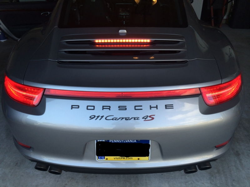
Porsche 991 C4S Third Brake Light Modification

991 DIY: Third Brake Light Modification

I am always looking to "tinker" with my toys, and can't leave well enough alone! Hence the following DIY.

I completed the following project about a year ago, never had a chance to post this up, but recent questions by members PorscheCrazy and others reminded me. Maybe someone will find this useful...   If you'd like to see a video of the blinking upper brake light in action, jump to the bottom of this post for a link to my YouTube channel GTSilver....

This DIY covers modification to my upper third brake light wiring to alter the LED from a single constant "on" steady state to a blinking light when brakes are applied.

Click the image to open in full size.

I actually got this idea from a member of a non-6Speedonline Porsche forum that is very popular. ;-)

I had always thought that having a blinking third brake light would be a great safety enhancement, and more so for smaller sports cars. SUV and mini-van drivers don't realize they just can't stop in the same short distance, this is for them or even those tailgaters and morons who love to ride up as close as possible to prove a point or something... 

Anyways, I found a small company that produces a controller that when tapped-into your brake light wiring modify from steady to blinking. The company is Kahtec Technologies International. www.kahtec.com This US company produces several products all focused on safety modifications for brake lighting. Someone recently mentioned that there are other products out there -- I do not have any knowledge of them or experience.

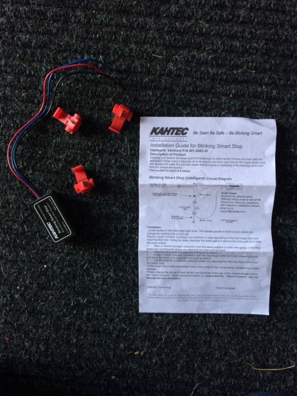
I went with the Kahtec "Intelligent" product, which when added claims to flash the third brake light 6 times rapidly when first hitting the brakes, then a steady 3 blinks every 6 seconds for as long you keep your foot on the pedal.

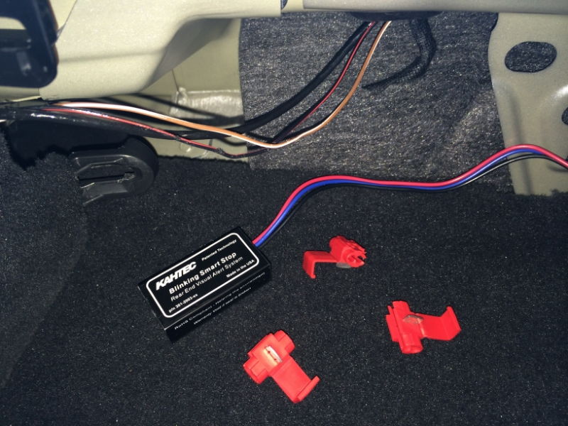
I ordered on the Kahtec web site, and in a couple of days the small box arrived as advertised. The box contained a small wired black box with Red, Black, Blue wires, set of wire taps, and instruction sheet.

Click the image to open in full size.

The instructions are very clear, easy to read and I felt comfortable that tapping into my wiring would be reversible should I have to switch back. So I set off in search of the best location to grab the wires in my car ('14 C4S coupe). I originally went about pulling the third brake light entirely from the rear vent grill lid (see my other DIY DIY: 991 Upper Third Brake Light Removal but after doing so, decided that there just wasn't a good location back there to mount the Kahtec black box. Also, Kahtec states that the box is NOT weather proof.

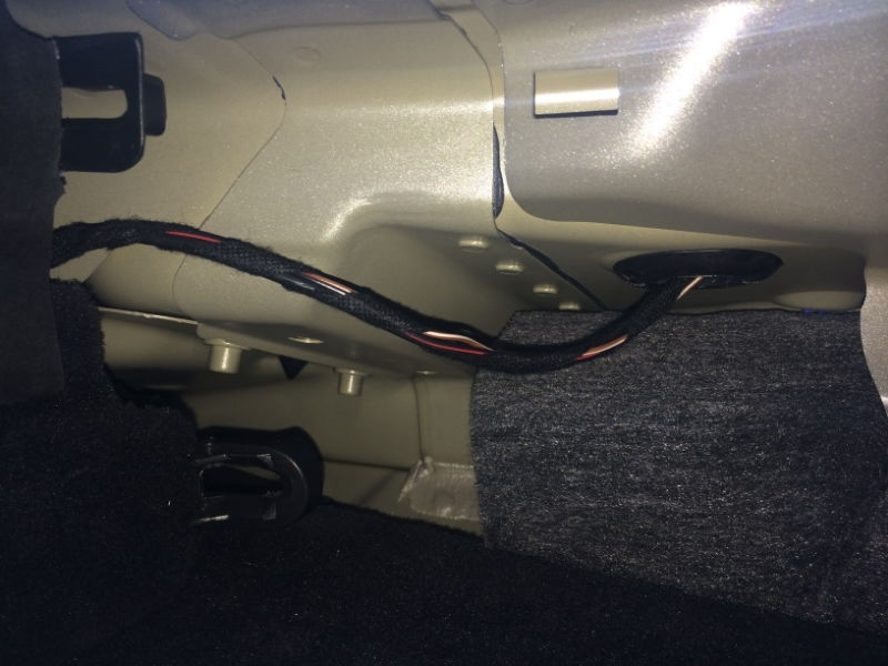
So, I recalled locating the wiring harness for the third brake light and antennae bump back when I was wiring my car for the back-up camera. I went back into the interior, passenger side under the back window... I pulled the trim off, and right in front of me was the wiring bundle I needed! It was great not to have to dig and search for wires for once!!

Here's the bundle -- there are three wires. Black/Red, Brown/White, and a larger solid black cable. The cables run from the passenger side of the car up into a rubber grommet (upper right side of pic below), which leads into the trunklid area and up to the grill where the upper third brake light resides.

For reference - in the pic below, LEFT is the passenger-side rear corner under window, RIGHT is near the Sound Symposer opening under the center of the rear window.

Click the image to open in full size.

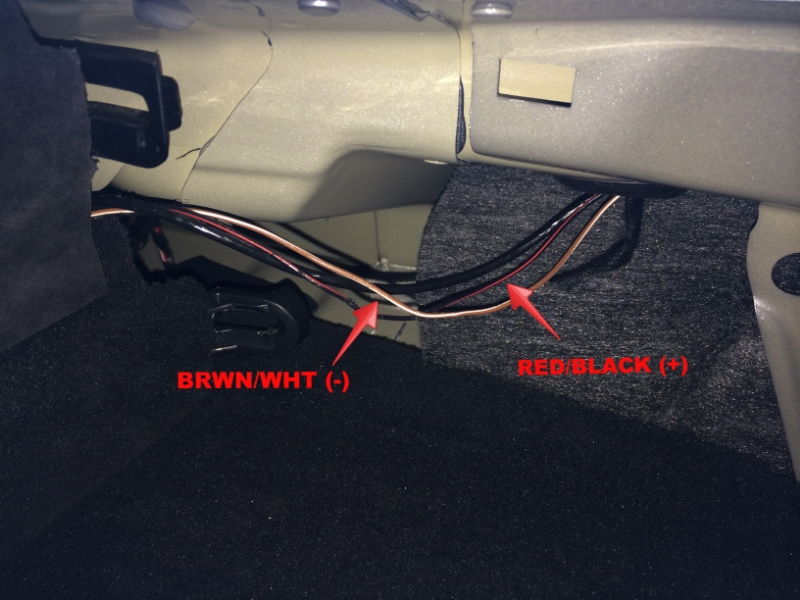
You'll need to slit the wrapping-tape to separate the wires...

Click the image to open in full size.

I quickly determined that BLK/RED is power (+) and the BRWN/WHT is ground (-). The solid black cable is for SAT/NAV antennae so I didn't mess with it (hmmm.... what project might I need THAT wire for???).

With the wires separated, the next few steps are easy to follow right from the Kahtec instructions included...

Get the Kahtec black box, and the three red plastic wire taps ready. (NOTE: I've since modified the wires further. I don't like using the clamp wire taps, so I went back and replaced with soldered bullet disconnects. Much more reliable, easy to disconnect if necessary, and will maintain a much "cleaner" connection. I'll post some new pics of the modification to the connectors when I get a chance.)

Click the image to open in full size.
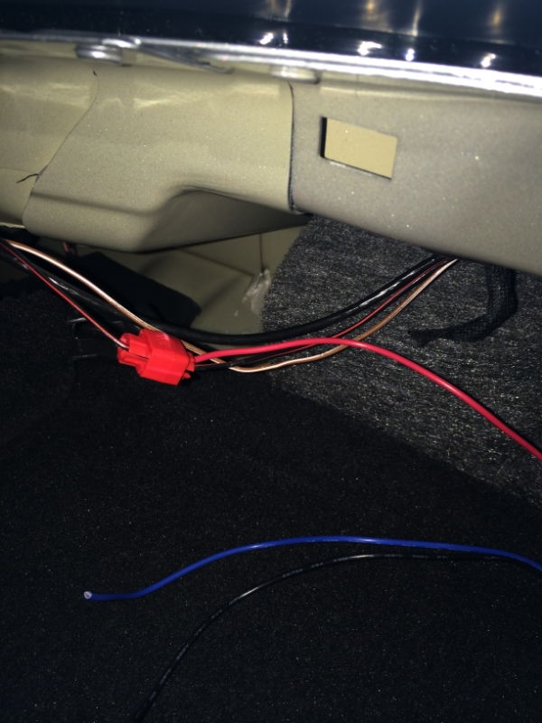
  • Hold the BLK/RED wire, pull it into the red wire tap.
  • Take the RED wire from the Kahtec black box and push it into the red wire clamp.
  • Clamp down on the red tap until you hear it "snap" and use a pair of pliers to make sure you've pushed through both wires.

Click the image to open in full size.
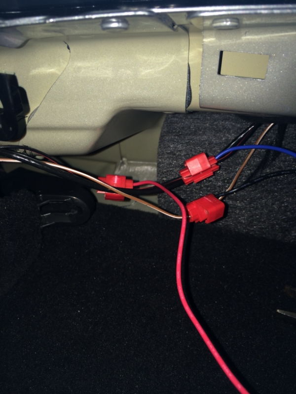
  • Now take hold of the BLK/RED wire about an inch away from the tap you just installed, and push the wire into another red wire tap.
  • Take the BLUE wire from the Kahtec black box and push the end into the red wire tap.
  • Clamp down to complete the splice connection.
  • Take the third red tap, and holding the BRWN/WHT wire push it into the tap.
  • Take the BLACK wire from the Kahtec box and push it into the red tap and clamp down.

Click the image to open in full size.

The last very important step? Make sure you follow the directions, and CUT the BLK/RED wire somewhere between the first and second red taps you just added in the steps above. Doing so now causes all power to run through the Kahtec black box to the upper third brake light. If you forget this last step, your brake light will continue to function as normal, without the blinking.

If for some reason you didn't get the wiring correct, you can disconnect the taps and re-try. Try to leave as much wire length as possible in case you need to restore to original state without the module. Also, when using clamp taps, it is possible that you didn't get a clean cut through both wires -- so if you are not getting the module to work, or you get any dash warnings about "third brake light not functioning" you can start your troubleshooting with the clamps.

If you take-on this project, please post your end results and experience here for all to share!

I have a video of the brake light blinking...  As well as the removal and setting everything back to "stock".  More on that later - but short story is I wanted to return the light to original factory before selling the car....  ;-)


Have fun!

Friday, March 4, 2016

Porsche 991 Vinyl Hood Wrap Removal

The other day I removed the 3M vinyl wrap from the hood of my 2014 991 C4S...  Created a short, "fast-forward" video for my YouTube channel (GTSilver - Please follow!).


As always, Thank You to everyone for their support!  Please comment below, and for more pictures, videos, and other stuff subscribe to my Twitter feed @GTSilver991!

Monday, February 8, 2016

Porsche 991.1 Plastidip Removal from Mirrors


I've had the mirrors on my GT Silver 2014 991 C4S sprayed in Plastidip Matte Black for the past year or so.  Decided to remove the 'dip as I am preparing for other projects.  To remove the dip I wanted to remove the mirrors entirely from the doors.  Thought I'd show you the process of removing the mirrors from the doors.  Might be useful for anyone wanting to send their mirrors out for painting, or wrapping, as well as for those who might want to swap their mirrors for another set....

Couple of things to note....  I have the standard 991 mirrors.  I do NOT have the power folding, Sport Design, or "GT3" mirrors.  However, I believe in any case the procedure to remove the mirror from the door is the same -- remove trim, a single bolt, and pull the wiring harness through the door.

Also, when I bought the car, the dealer had already installed xPEL PPF, and there are small pieces on the mirrors.  When I sprayed with Plastidip, I just sprayed right over the film.  So, I really wasn't sure if the 'dip was going to bond or "merge" and stain the clear film.  But actually what I found is that the 'dip spray peeled-off more easily from where the film was than where it was not!  As you can see in the video I shot, the 'dip peels off real easily from the mirrors.  Each mirror took me about 30 minutes to peel and clean-up.  Where I had difficulty peeling, I simply brushed on some Xylene and wiped the 'dip off!  Very easy!

I continue to be impressed by the durability and versatility of Plastidip!  It is amazing stuff.  My car is no garage queen, so seeing first-hand how it protects the car I am a true believer!

Here's the video posted up on my YouTube Channel - GTSilver....  Please subscribe for more!


Tuesday, January 12, 2016

DIY: Porsche 991 911 C4S Inner Door Panel Removal and Installation

Hi All-

I've put together a YouTube video showing how to remove the full inner-door panel of my 2014 991 C4S.  The procedure for ALL 991 model years and configurations is the same, and I believe this also applies to the 981 platform as well.

I had to add narration after the video was shot -- too much background noise at the time made it hard to record.  If you need additional guidance, let me know.  I also have step-by-step written instructions.

The procedure is really quite simple, and even for the novice is very low-risk and you should be able to get the full panel off within 10-15 minutes using this video...

Enjoy!

Porsche 911 991 C4S Inner Door Panel Removal & Installation


Sunday, January 10, 2016

Porsche PIWIS TSI Walkthrough

I just posted a new video up on my YouTube Channel:


This is a somewhat rambling walkthrough / overview of the official Porsche PIWIS TSI, or Porsche Integrated Workshop Information System - Technical Service Information.

I posted an index recently of all the Work Manuals and some other reference documents I've used over the past year or two working on my own 991 -- thought this might also be helpful to others who like to get their own hands dirty.

Thanks!

Thursday, December 24, 2015

Plastidip Touch-Up: 991 C4S Wheel

As posted in my "Removing Plastidip" post, I am also touching-up the other three wheels on my '14 991 C4S.  Mounting snow tires for the NE winter caused some of the matte black dip on my 20" wheels to pull-up.  Although in the previous post I was stripping the Plastidip from the wheel before respraying, I only needed to do that for the single wheel.  The other three wheels had only minor pulls or rips in the black dip coating -- so I chose to clean the wheel up and respray.

This video (a bit better quality this time!) captures the process I followed to get each wheel back to "new".

Appreciate any feedback / comments!

Plastidip Touchup and Respray


For the previous post, check out:  Removing Plastidip from 991 C4S Wheel

Wednesday, December 23, 2015

Plastidip Removal: 991 C4S Rear Wheel

I posted a (lame...) DIY video over on my GTSilver YouTube page:


The Background:

Short story is that I have had my '14 Carrera Classic wheels painted with matte black Plastidip for about a year now.  I just had new tires installed, and the process of doing so pulled some of the 'dip off.  The drivers side rear was in the worst shape and I decided to strip the whole wheel face and reapply.  The other three just needed minor touch-ups and a respray.

I am loving this stuff...  Even with harsh weather of all kinds, and many washings, the Plastidip on the wheels has held-up extremely well.  I had one small instance months back where I had a "chip" in the "dip", and that was easy to fix without refinishing or painting the whole wheel.

I'll post another vid and more on the touch-up process later....

I have never removed Plastidip before, so went into this project with my fingers-crossed.  I found tons of videos and online descriptions about painting wheels with dip, but very little on removing.  So I decided at the last second to record my work on video, using my iPhone 4S.  I know, the quality is crappy, and editing is very poor.  I'll work on improving as I do more videos.

Removing Plastidip from Wheel:

The video is self-explanatory.  I start-out peeling by hand, then try a heat gun, then WD-40.  All worked, with the WD-40 being very effective without any harm to the underlying wheel finish whatsoever.  While the peeling by hand method works, and applying heat made peeling a bit easier, the WD-40 method was super effective and I probably should have started there.

Totaling the time I spent stripping, cleaning, and respraying this one wheel I realize it is not a "quick" process.  I believe I spent several hours just getting to a point where I was applying new dip.  But this was my first time, and I was experimenting (and trying to video with one hand and work with the other), so I don't think next time it will take me nearly as long.


As I was starting the respray, my phone memory hit a wall, so the video abruptly cuts off...  but you aren't missing much.  I applied something like 7 coats, going heavy as I want the next time I have to strip the dip to be easier.

Happy to answer questions, provide more details if it would help you!  Just reply / comment on the video or this post.

Thanks!


Wednesday, May 6, 2015

991 DIY: Removing / Installing Front 3-Point Seat Belts

Following is a brief DIY for those of you out there who want to swap their factory three-point seat belts for different color, need to remove the seat belts for another project, replacement after an accident, etc.  I don't have any pictures at this time, sorry.  This will have to be purely a description DIY until I can find some time to do this on my own C4S.

Let's go!

Preparation:

  • You will need to have an assortment of Hex and Torx bits, sockets and a screwdriver available.  I don't have all of the individual sizes available at the moment.
  • Have a set of plastic interior trim tools handy.  You will need to remove the trim covering the belt assemblies, etc.
  • Disconnect the negative (-) terminal to the battery!  You must do this to avoid any issues with the pretensioner unit, either triggering or throwing fault codes.  Also remove the key from the ignition (if you have keyless entry, remove the starter key from the dash).  I have read various opinions on whether this is necessary on the modern P-cars or not, but why take the risk?  The official PAG Workshop Manual (WM 691119) instructs the disconnection of the battery, so I say do it!
Note:  The seat belt pretensioner unit is no longer usable or safe once it is triggered.  The unit triggers an explosive charge to lock the belt when there is an accident, and should then be replaced.  It works in conjunction with the Airbag (except in rear-ender where the airbags won't fire.)  If you need a replacement, you can order from authorized Porsche parts suppliers.

  • Lastly, You are going to be working in some tight spaces.  Consider whether it would be a whole lot easier for you if you remove the front seats entirely from the car.  Totally something even the newbie DIY can tackle, and will make your life a lot easier.

Step 1: Remove B-Pillar Trim

  • Loosen the three-point set belt bolt found at the bottom near the door sill.  There is a small black plastic cap covering the bolt.
  • Using a trim tool or your fingers, grip the belt "collar" trim piece on the B-Pillar on the sides and pull directly out from the pillar. 
  • Release the unlocking bracket on the clamps and pull it forward.
    • You may need to use a pointy tool or wire hangar bent to release from within the pillar...
  • Slide the trim piece down the belt out of the way (exposing the seat belt mounting points which were concealed by the trim piece).

Step 2:  Remove the Rear Side Panel Trim

  • You may want to remove the C-Pillar trim piece (upper trim piece where the rear seatbelt enters the roof-line belt collar - and you will need to remove this piece if you are replacing the rear seat belts...) first.  The trim pieces for the side panel, roof panel, and C-panel all come together back there, and it may be less risky to remove the C-pillar trim first.
  • Remove the rear seat cushions -- you can just lift up and pull forwards.
  • Unscrew the rear seat back locking pins from the side panel -- using a socket or drill with appropriate bit ( I believe this is a T25 bit), unscrew the locking pin and place aside.  This is the only fastener holding the panel in place.
  • Grabbing the side panel trim at the bottom and top, pull the side trim panel up and swivel it inwards from the top towards you.
  • Disconnect the electric connector to the side panel speaker
  • Pull the backrest bearing collar inwards and off.

Step 3:  Unfasten Front Seat Belt Mounts

  • By the door sill, locate the lower mounting point of the front seat belt, which you loosened previously.  There is a plastic cap over the bolt --  remove the protective cap.
  • Using an appropriate Torx, unscrew fastening screw and remove belt fitting and spacer sleeve.
  • At top of the belt, at the B-Pillar, use your Torx to unscrew and remove fastening screw.
  • Pull the belt strap out of the guide bar.

Step 4:  Remove Seat Belt Pretensioner Unit

  • Moving down the B-Pillar, locate the Pretensioner unit.
  • There is a single fastener holding the pretensioner unit to the pillar.
  • Using your Torx, unscrew the fastener.
  • Pull the pretensioner unit up and out of the pillar.
NOTE there are electrical connection(s) to the pretensioner!  There are variants, based on geographic region.  Following is for USA.  Rest of world there is only a single electrical connection -- I can't confirm this, but if you find one or more connectors, they all work the same way.
  • Release the locks on the electric connectors (USA) on the seat belt pretensioner using a screwdriver.
  • Disconnect connectors
And you now should have the entire seat belt assembly removed from the car.  Carefully wrap the removed / stock pretensioners and seat belts and store someplace safe -- or if the pretensioners have already been triggered slice the belt and toss since like an airbag, the pretensioners shouldn't be reused once triggered.

To install new belts and pretensioners, follow the above steps in reverse order.  Also, note that when hanging the new belts, you will want to "turn" the lower mounting plate of the belt 180 degrees before fastening-down.  

If you are tackling this project and take some pictures, I would be happy to post them and give you photo credits!  I think some pictures of the pretensioner, trim panels removed of that area would be very helpful to others!


Tuesday, March 31, 2015

DIY: Porsche 991 911 Rear Side Window Removal and Installation

(Posting this up without all of my pics for now -- can't find 'em.)

I had an opportunity not long ago to assist in the removal and installation of a rear side window on a 2013 Porsche 991 Carrera.  More recently, a 6Speedonline / Rennlist forum friend reminded me that I never posted the step-by-step online.  So here we go, I'm finally getting-around to it!

Following are the steps required for removing the rear side window and installing a new unit.  While this was a replacement, if for some reason you needed to remove an undamaged window, the steps are the same and you can simply re-install the existing window unit.

First, a few notes to prepare for the project:
  • If you are replacing the rear side window, know that the glass and lower edge trim are provided as a single part -- you can't just buy the trim piece separate from the glass, you have to order the "kit" which is a factory-installed glass and trim unit.
  • The lower trim moulding around the side window is not removable from the glass assembly.
  • To remove the glass assembly from the car, you will have to remove the roof trim moulding along the upper-edge of the window, as well as the B-Pillar interior trim panel.  I will describe those in the steps below.
  • Be very careful with the roof trim moulding, as it is very easy to bend, kink, and scratch.  Otherwise, have a new part ready to replace the one you mangled!
  • When installing the glass assembly, you will have to adjust the window glass so that it is aligned perfectly on the x-and-y axes of the forward window panel.  This is a bit tricky but take your time and it will look great.  You need to get the side window glass flush at the surface plane but also the gap between the rear and front glass panels must be perfect or the window looks a bit crooked.  Hint:  Get a measurement of the gap between the two BEFORE you remove, and keep that handy.  What I did that worked great is to find a small piece of cardboard, or rubber sponge, something you can mark and cut it into a gap template and use after the new glass is installed to check the gap from top-to-bottom -- I'll go over this in more detail later.
You will need the following for this project:
  • Torx with T-20 star bit
  • Metal shaft with 90 degree bent tip (or something similar for releasing B-pillar clamp)  
  • Microfiber towels
  • Painters tape
So let's get started!  I've snapped a few reference pictures  (NOT from the replacement project I did recently) from my own 991 and will use these to point-out where the fasteners are and so on....

Start on the exterior of the car.  With the door shut and window fully raised, you should get a measurement of the gap between the front and rear side windows.  You don't have to do this, but later in this DIY when you install the new window it will help you with the alignment of the rear side window.  To create a gap tool, take a piece of cardboard, or something similar, and hold it flat to the gap.  Take a pen and mark the the edge of front and rear windows.  Slide the template down along the gap to check consistency of the gap.  Once you have the measurement, you can notch the template so that you have a simple "tool" to check the gap.  More on that later.

Step 1:  Roof Trim Moulding Removal

You need to remove the roof trim moulding that runs from the windshield back to the rear window.  This is a single piece.  Blue arrows in pic below indicate the trim piece to remove...


To do this you will need to do the following:
  1. Pull rubber door seal from the areas indicated in the next picture.  The rubber seal comes away from the frame very easily -- no adhesives or anything to worry about.  You need to pull it down and out of the way, and completely off if you want to protect it.  It is a single rubber piece that could easily get crimped if you are not careful;  
    Pull down, and near the door corner begin pulling towards front of the car as you pull down...
  2. Get a Torx tool with T-20 tip.  Along the front section of the moulding that you just exposed by pulling the rubber door gasket down there are 8 small clamps that you need to turn 90 degrees to release the moulding.  
    Small plastic fasteners are easy to break -- gently turn them 90 degrees. 
    These are small plastic parts that break easily so take your time and don't force or you will need to replace them;  
    After pulling rubber door gasket down, the moulding fasteners are along edge inside the gap.
    There are a total of 8 small plastic fasteners for just the front section of moulding.
  3. Once you release all 8 clamps, start at the front, and slowly pull the trim down towards the ground, away from the roof -- NOT forcing it or bending, just free from the clips you loosened in step 2.  As you pull the trim down, get a body trim tool plastic wedge and put it between the trim and the car body to keep it away....  The moulding is stiff.
  4. At the rear section of the trim, there are (3) three larger clamps.  Sorry I don't have a picture of these....  You need to release these to get the trim fully removed.  They are like hangar-clips that the trim piece snaps down onto.  Starting at the B-pillar, begin pulling the trim free of the clamps, at the same time sliding it forwards, away from the joint where the upper trim connects to the lower part.  
    Circled the joint in the trim where front section separates from trim fixed to window.
    Be careful with the trim piece as you pull it away from the car entirely, as it is somewhat flimsy.  Find a safe, soft place to put it, and perhaps even cover it with a nice comfy blanket or something!
Step 2:  B-Pillar Interior Trim Removal

The B-pillar interior trim panel must be removed to access the release / alignment bolts.
  1. You may want to loosen or even release entirely the seat belt at the bottom mounting position to give you some more slack;
  2. Pull the belt collar trim (the small plastic part with a slot where the belt disappears into the trim) away from the B-pillar trim.  You can put your fingers into the slot and pull up while pulling out from the pillar and it should just pop off;  
    The belt "collar" comes off easily and you can slide it down to the floor out of the way.
  3. Pulling from top and bottom (interior trim tools work best), pop the B-pillar trim / cover away from the pillar.  There are 3 small pins that snap into the pillar - one at the top and two at the bottom.  But in the middle, just above the opening for the belt collar, there is a clamp that must be released by poking it from "inside" the B-pillar.  Porsche has a special tool for this, which is just a handle with a metal shaft bent at the end.  I found a picture of the tool shown above.  The tool must be inserted in a hole just below the clamp location, just above the bolt holing the seat belt to the pillar, and then angled up and turn to press the tip of the tool against the clamp to release it from "inside."  Hard to describe the motion -- but any tool with a similar tip could be used.
  4. With the clamp released, you can now pull the B-pillar trim away, and if you haven't released the seat belt, just let it slide down out of the way.
Before we move on, just a few comments.  First, if you've made it this far without breaking anything, you are doing awesome!  The clips/clamps and moulding are fragile, and you might break them.  But just keep in mind that the hardest part is now out of the way!  

You may also want to consider removing the C-pillar and rear side trim panel (directly below the window) but they are not mandatory.  Also, if you don't remove the rear side trim panel, you may want to put some microfiber towels, or painters tape down along the bottom edge of the rear side window  to protect the panel from any scratches, scuffing, etc. as you remove / replace the window assembly.  If you do want to remove either trim pieces, and would like a DIY post on doing so, just let me know....

Step 3:  Rear Window Removal

With the moulding and trim removal out of the way, you can now focus on removing the rear window assembly.  There are only two (2) fasteners actually holding the window in place -- the rest are just guide tabs!
  1. Unscrew the two mounting / fastening nuts on the B-pillar;
  2. With the fasteners removed, gently push the window from the interior near the front of the window until the two positioning pins are free of the B-pillar;
  3. At the same time you are pulling the window towards you away from the car body, note there are a few guide pins (top / bottom of assembly).  As you clear the pins from the body, begin carefully pulling the entire window assembly towards the front of the car.  There is a "slot" pin at the rear of the window assembly trim that slides into a slot in the C-pillar area.  This is the final point of contact that you need to clear.
  4. Take the entire window assembly away from the car....  If you are re-using this assembly, I would recommend wrapping it up in a blanket or towels to protect it.
You are done!  You should have the moulding, trim, and window assembly safely stored somewhere until you need to replace.

Before we get to the installation part -- now is a great time to thoroughly clean all the nooks and crevices around the door, window, and roof trim that you normally would never be able to reach during even a concourse detailing session.  Wipe all down with cleaner of your choice, and maybe even a bit of wax, like detailers wax.  But if you don't really care about things like this -- just skip it!

Installation:

All of the removed parts are installed by simply reversing the steps outlined above.  The re-installation of the roof trim moulding is a bit difficult, as you have to get it aligned perfectly to avoid having a crappy-looking external joint near the back of the side window.  I've seen a few cars on the dealers lot that look a tiny-bit "crooked" or not fully aligned.  So take your time and hopefully you'll have a good time with it!

When re-installing the rubber door gasket, take your time and make sure that it is slotted properly around the entire perimeter.  The tricky section is the right-angle between the B-pillar and roof line.  You may need to force it in a bit, but make sure it is not folded-over or creased when doing so.

However, one step that you will need to go through is alignment of the rear window.

Window Alignment:

Once you get the rear window assembly mounted back into the body, you use the two positioning pins to move the glass into the proper position before tightening-down the fastening nuts.
To do this, get your tool that you used to mark the gap between front and rear side windows.  Move the rear window around until you have the correct gap top-to-bottom between the two windows.
At the same time, you should make sure that the edges of the two windows are on the same plane -- ie so you don't have the rear glass edge sticking-up higher than the front window edge.
Once you feel the glass is aligned to perfection, tighten-down the two fastening nuts on the interior of the B-pillar.

And that's it!  You should now be able to put all the trim bits back together and finish-off another successful project.  

If you found this helpful, please "Like" and comment.  Appreciate any and all feedback!  Also don't forget I am open to suggestions for other projects if you have a  need, comment / contact me through this blog.

Thanks!


Monday, March 16, 2015

Porsche 991 911 Center Console Switch Box Deconstruction

Porsche 991 911 Center Console Switch Unit
Here's another one for all fellow "tinkerers" out there...  I have been thinking about how the 991 center console switches function, and what one might be able to do with the "blanks" that all of the 991 models seem to have (I have seen fewer blanks on a GT3, but nearly all other 991 models have at least 3 blanks in the console switch unit).

What follows is a step-by-step breakdown of the center console switch module from a 991.  In this particular case, the donor did not have PSE (Thanks for fellow member for donating!).

My thinking is this... that although the unit is a single controller, we should be able to figure-out how to modify the switches in order to do something with the blank spots, such as build-in custom switches for radar, other accessories that one might want to install.

The challenge in doing anything with this console module?  It is a single control board, with various switches mapped and likely programmed specific to the car and its' options (ie when you add PSE they replace the entire switch unit, not just add a single switch).

In the "old days" you could pull a single, isolated switch from the dash or console, and replace with something else, or at least gain direct access to specific wires and such going to the accessory buttons.  Nowadays, all of the switches are on a single circuit board, and tie-in to the car network (CAN) through a couple of wires and a connector.  So you really can't just move the switches around, remove something and replace with a different function, etc.  At least not yet...  LOL

Let's get to the deconstruction.

You need to remove the switch module from the center console, so if you haven't already you should review the DIY I posted previously on just how to do this.


So if you've followed the removal DIY, disconnected the cable running to the switch-box, you should be holding the 'black box' at this point.  Here is the module sitting on my bench...

This is the "underside" of the switch box.
Note the part #'s S/W and H/W versions
After you have the module on your bench, flip it over so you are looking at the "bottom."

There are 6 torx head screws that you need to remove, as indicated in the following picture.

The small screws removed....
Using the smallest T bit that I have I removed each one and set aside...  These are small, so if you have a tray or even a small plastic sandwich bag you should put them in a safe place.  Would hate to lose one of these buggers!

With the screws removed, gently pull-up on the the back-cover and put aside.  You'll find as you separate the back from the main assembly that there is a rubber gasket layer sandwiched in there (covering the circuit board) - you'll notice it in the area where my thumb is in the following pic.


Place the back cover aside.  In this picture, you can see what you've exposed is a single circuit board.


Now pull-up gently on the circuit board, separating it from the main assembly.  Do so carefully, as in the picture below you'll find that there is a spring in the center -- don't lose that!

Red arrow indicates a small spring in the center of the assembly.
Have something handy, like a small bowl or plastic bag, to put the small bits in.  Place the circuit board to the side.


Since the "top" of the switch box assembly is face-down on your table, you are now looking at the underside of the switch actuators....

I've indicated where the "blanks" are so you can see the difference
between those and the actual "live" switches from the console...
The first observation about this is that given the space under the dummy switch covers (effectively they are hollow) it is very possible that an aftermarket / custom switch assembly can be added.  More on that later.

Let's move over to the circuit board for a moment....


On one side you see the standard green board with some chips and other bits visible.  Flip it over and on the other side is a rubber gasket of sorts...  You can pull that off - there isn't anything holding it in place that you need to worry about.


The small metal discs correspond to the switch contact points, which in turn are mapped to the corresponding circuits for controlling specific features / functions of the car.  This is all via CAN-BUS and programming, so if you were expecting to be able to tap into specific wiring for a switch you are out of luck!  These are pressure sensitive contact points, and represent either an ON or OFF state....  The rubber gasket is effectively protecting the circuit board and contacts from any moisture, such as when someone might spill or drip beverages onto the center console.  Might make for some sticky buttons, but looks to me like there wouldn't be much chance for shorting or other electrical problems!

Back at the "rear" of the switch console box -- you can remove the three grey assemblies, taking care with the center one which has a spring.  The plastic bits literally just fall-out so nothing tricky needed for removal.


In the case of my car the switch buttons are to control the metal sunroof.  Open / Close / Partial settings and corresponding buttons.  If this were a cab car, I would expect these buttons to control the top open / close functions.  In a coupe with NO sunroof option?  Not sure what would be there. Probably just blanks.

To remove one of the buttons that are already in place, you will need to push it out from the rear.  I used a small micro-screwdriver and gently pushed until it popped-out a bit and I could pull it the rest of the way out.


Here's a pic of the switch face plate or cover removed...


The face plate is a small thin black plastic part with a small hole in the corner (for the red indicator light).  NOTE that the face plates are right - or - left side specific.  For example, the PSE button can only be installed to the right bank of buttons...


Once you have the switch face plate removed, you can remove the chrome plastic bit from the front of the console box.

In the following picture, you can see the "dummy" or blank button face removed, with the small chrome bit removed from the "real" button just above.


Here you can see the difference in a "dummy" button  (circled in red) and "real" or working button (upper space in the pic below) when the faces of the two buttons are removed.  In the functioning button, note there is a black "box" of sorts inserted, which when face is on and pressed contacts with the actual contact switch on the circuit board.


You can remove the black plastic "box" in a switch by gently pressing on it from the face side to push it out the back of the console box.  And do the reverse if you are inserting a new button....


Following is a pic showing the two buttons on the right that have been completely removed from the switch box.

And from the reverse side....


Pic of the various bits deconstructed and laid-out on the bench.


So, you've deconstructed your center console switch box...  What can we do with this information???

Well, I didn't do anything.  I simply put it all back together again.  But, I now know that if I really wanted to add a "custom" switch integrated to look factory installed I could.  It isn't going to be fully-integrated at an electronics communication level (CAN BUS), but a physical integration with the switch face plates.  To add a custom switch, you will have to create an access port into the space directly under the switch face plate you are customizing.  This means drilling a small hole on the side of the console box and routing your wiring through and into the space directly below the switch box.

Of course, until someone does this and shows in detail, it is just a concept.  Couple of other things to know -- You can purchase a switch repair kit from Porsche that includes replacement switch face plates, switch console box, and other bits.  I think this currently runs about US $225 or so.  Also, this kit is needed whenever an owner adds Porsche Sports Exhaust to their car, as the kit includes the new button to turn the PSE on and off.  Here is a pic of the kit (swiped this from an online marketplace):


Note also that the switch repair kit does require a match to your VIN -- in the example pic above, this kit was obviously for a car that is NOT a convertible, and doesn't include the metal or glass sunroof option, since there are no buttons for roof control in the middle of the switch panel.  So check your VIN when you order a switch repair kit.  And no, getting a kit with the additional buttons DOES NOT mean that by installing you will magically have PDCC, front lift kit, PSE, or a convertible!!!!  LOL.  These are replacement buttons and other parts, but you will need to get any programming done by the dealer (or independent with the PIWIS tool and the option codes for your car from the factory).

Anyways, this is a LONG post -- sorry all!  I've run out of steam.  Happy to answer any questions if you want to post them.  I also have a spare switch kit that I can dig into in more detail if you have any questions.

Thanks!