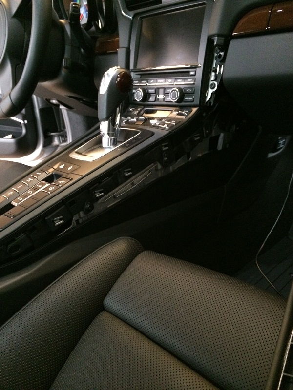
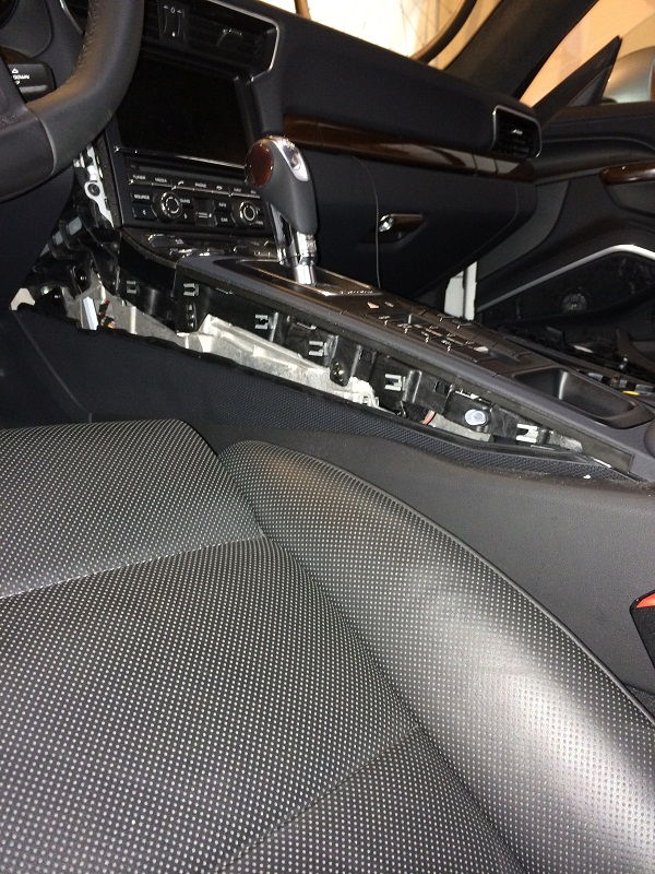
Just a quick post to help a fellow 991-owner out... I've previously posted DIY about removing (most) of the center console trim (for the purpose of removing the switch panel, as well as PCM head unit). What I didn't cover was how to remove the 991 PDK shift knob or the trim piece directly around the base of the PDK.
So, without further boring dialog, here goes...
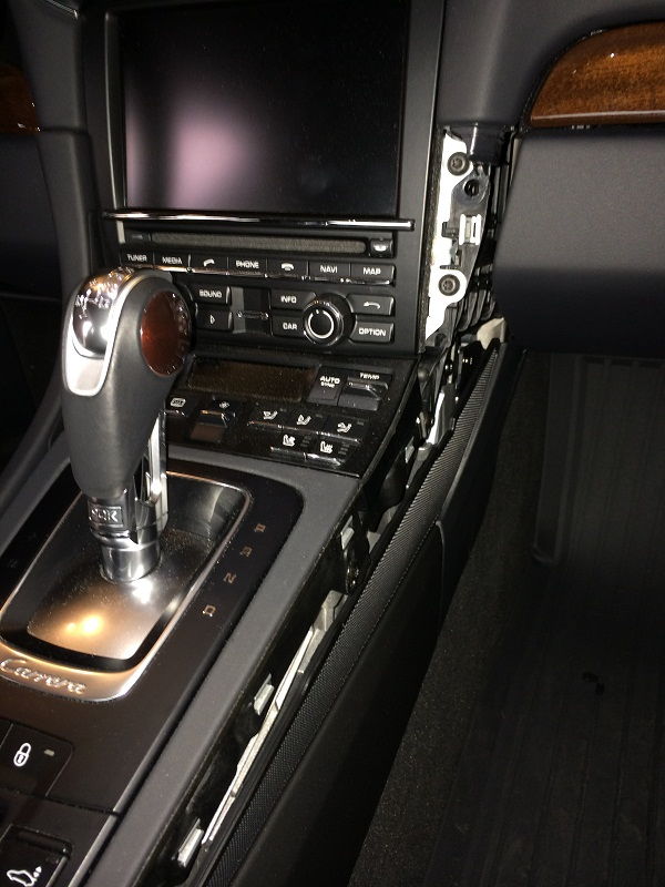
Remove the center console side trim pieces. You don't need to remove the switch panel directly below the selector trim piece, but you should remove at least the side panels and console trim. If you do remove the switch panel, it just gives you that much better access to the plug for the hazard light switch and leverage to pull up.... For details, see my other DIY post for center console trim at 2014 Porsche 991 Center Console Trim PanelRemoval
Remove the PDK selector knob.
At the base of the PDK selector shaft, there is a locking ring -- turn that to the right. MacCarbon has a decent DIY for replacing the selector knob (with their CF version) and suggest you might need to put some blue masking tape on the ring to gain additional grip.
Push the knob button at the top forward and pull upwards, releasing it from the selector shaft....
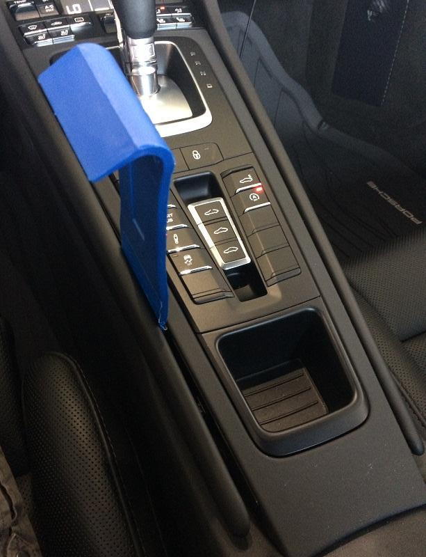
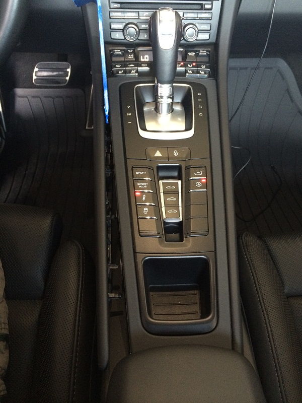
Remove the upper part of center console... This is the trim around the selector "gate" which includes the model designation label and hazard / locking buttons. Note that this is a single trim piece and will be lifted-off over the gear selector shaft.
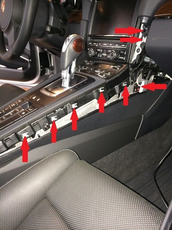
Unclip cover by pulling it up in the direction of the arrows in this picture:
Lift up the cover at the front so that you can easily access the switch connection for the hazard lights;
Pull-off the connector for the hazard warning light switch as shown in the picture below:
Lift the cover trim piece up and over the selector shaft....
You should now have the trim piece free of the selector shaft, and ready to replace with another piece, etc.
Hope this helps!
I am always looking to "tinker" with my toys, and can't leave well enough alone! Hence the following DIY.
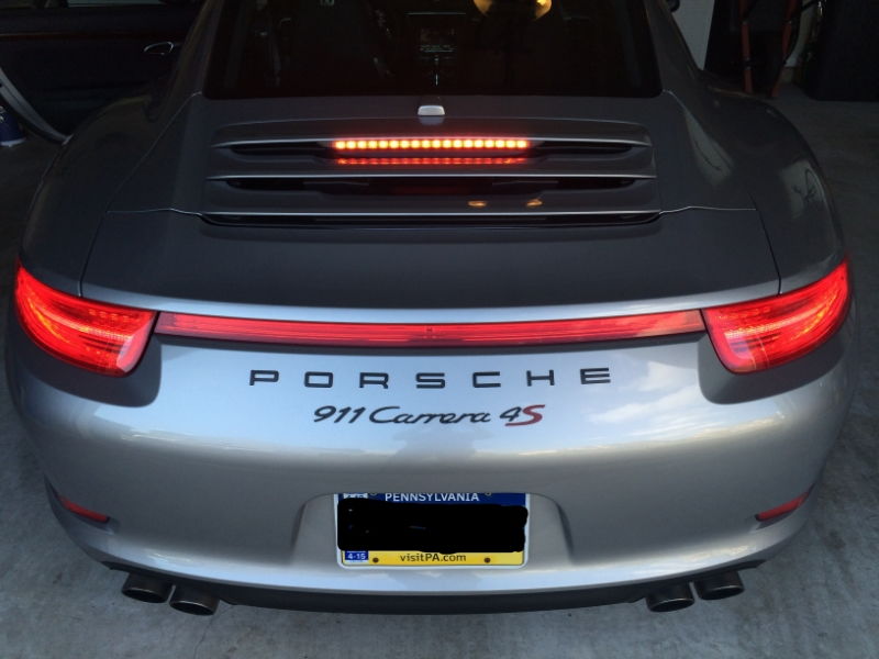
I completed the following project about a year ago, never had a chance to post this up, but recent questions by members PorscheCrazy and others reminded me. Maybe someone will find this useful... If you'd like to see a video of the blinking upper brake light in action, jump to the bottom of this post for a link to my YouTube channel GTSilver....
This DIY covers modification to my upper third brake light wiring to alter the LED from a single constant "on" steady state to a blinking light when brakes are applied.
I actually got this idea from a member of a non-6Speedonline Porsche forum that is very popular. ;-)
I had always thought that having a blinking third brake light would be a great safety enhancement, and more so for smaller sports cars. SUV and mini-van drivers don't realize they just can't stop in the same short distance, this is for them or even those tailgaters and morons who love to ride up as close as possible to prove a point or something...
Anyways, I found a small company that produces a controller that when tapped-into your brake light wiring modify from steady to blinking. The company is Kahtec Technologies International. www.kahtec.com This US company produces several products all focused on safety modifications for brake lighting. Someone recently mentioned that there are other products out there -- I do not have any knowledge of them or experience.
I went with the Kahtec "Intelligent" product, which when added claims to flash the third brake light 6 times rapidly when first hitting the brakes, then a steady 3 blinks every 6 seconds for as long you keep your foot on the pedal.
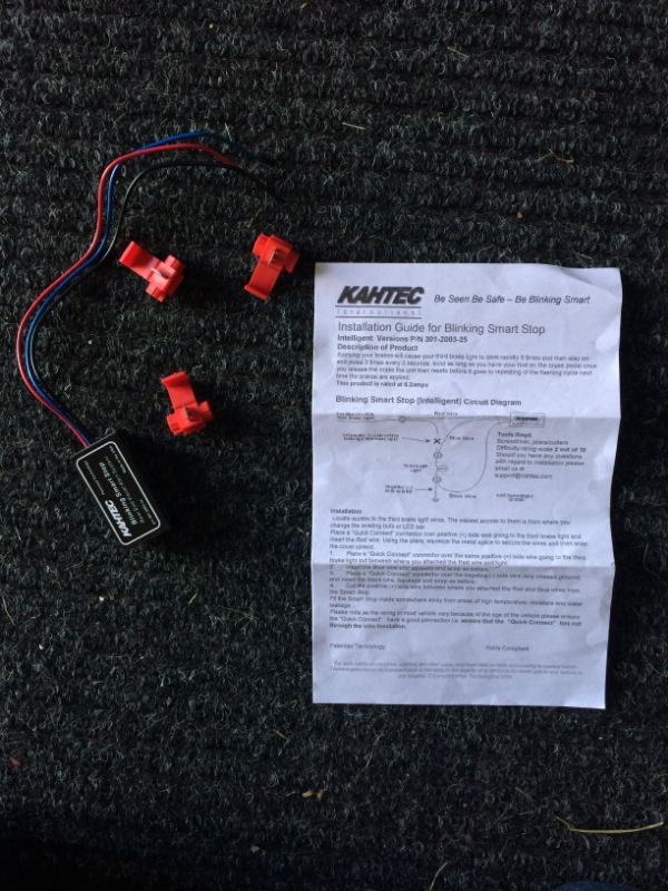
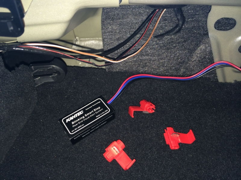
I ordered on the Kahtec web site, and in a couple of days the small box arrived as advertised. The box contained a small wired black box with Red, Black, Blue wires, set of wire taps, and instruction sheet.
The instructions are very clear, easy to read and I felt comfortable that tapping into my wiring would be reversible should I have to switch back. So I set off in search of the best location to grab the wires in my car ('14 C4S coupe). I originally went about pulling the third brake light entirely from the rear vent grill lid (see my other DIY DIY: 991 Upper Third Brake Light Removal but after doing so, decided that there just wasn't a good location back there to mount the Kahtec black box. Also, Kahtec states that the box is NOT weather proof.
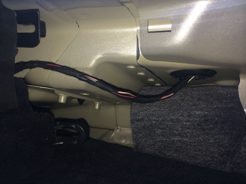
So, I recalled locating the wiring harness for the third brake light and antennae bump back when I was wiring my car for the back-up camera. I went back into the interior, passenger side under the back window... I pulled the trim off, and right in front of me was the wiring bundle I needed! It was great not to have to dig and search for wires for once!!
Here's the bundle -- there are three wires. Black/Red, Brown/White, and a larger solid black cable. The cables run from the passenger side of the car up into a rubber grommet (upper right side of pic below), which leads into the trunklid area and up to the grill where the upper third brake light resides.
For reference - in the pic below, LEFT is the passenger-side rear corner under window, RIGHT is near the Sound Symposer opening under the center of the rear window.
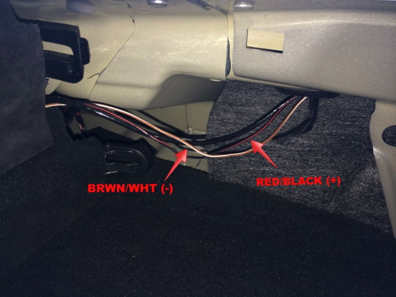
You'll need to slit the wrapping-tape to separate the wires...
I quickly determined that BLK/RED is power (+) and the BRWN/WHT is ground (-). The solid black cable is for SAT/NAV antennae so I didn't mess with it (hmmm.... what project might I need THAT wire for???).
With the wires separated, the next few steps are easy to follow right from the Kahtec instructions included...
Get the Kahtec black box, and the three red plastic wire taps ready. (NOTE: I've since modified the wires further. I don't like using the clamp wire taps, so I went back and replaced with soldered bullet disconnects. Much more reliable, easy to disconnect if necessary, and will maintain a much "cleaner" connection. I'll post some new pics of the modification to the connectors when I get a chance.)
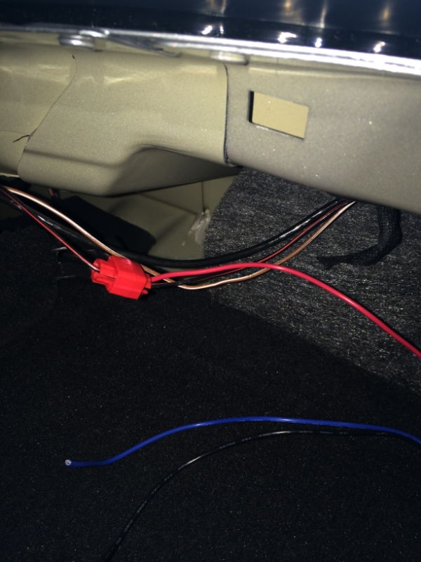
Hold the BLK/RED wire, pull it into the red wire tap.
Take the RED wire from the Kahtec black box and push it into the red wire clamp.
Clamp down on the red tap until you hear it "snap" and use a pair of pliers to make sure you've pushed through both wires.
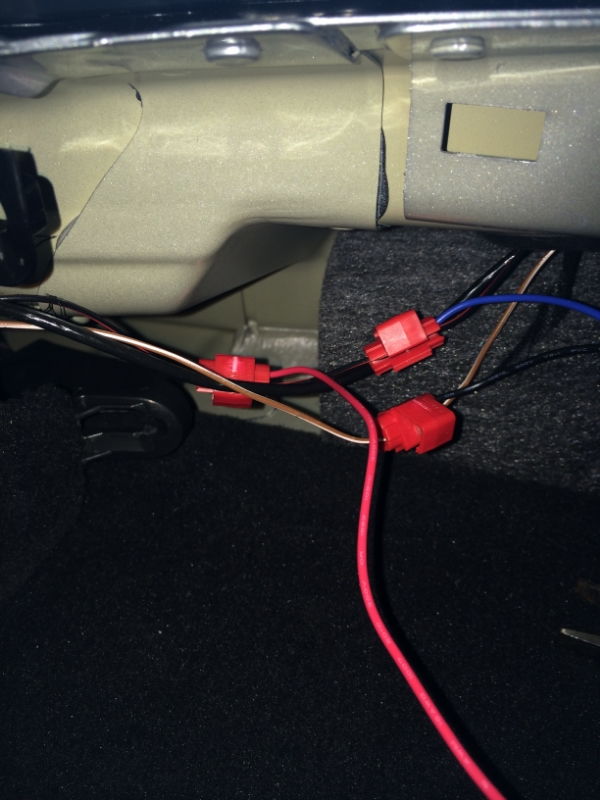
Now take hold of the BLK/RED wire about an inch away from the tap you just installed, and push the wire into another red wire tap.
Take the BLUE wire from the Kahtec black box and push the end into the red wire tap.
Clamp down to complete the splice connection.
Take the third red tap, and holding the BRWN/WHT wire push it into the tap.
Take the BLACK wire from the Kahtec box and push it into the red tap and clamp down.
The last very important step? Make sure you follow the directions, and CUT the BLK/RED wire somewhere between the first and second red taps you just added in the steps above. Doing so now causes all power to run through the Kahtec black box to the upper third brake light. If you forget this last step, your brake light will continue to function as normal, without the blinking.
If for some reason you didn't get the wiring correct, you can disconnect the taps and re-try. Try to leave as much wire length as possible in case you need to restore to original state without the module. Also, when using clamp taps, it is possible that you didn't get a clean cut through both wires -- so if you are not getting the module to work, or you get any dash warnings about "third brake light not functioning" you can start your troubleshooting with the clamps.
If you take-on this project, please post your end results and experience here for all to share!
I have a video of the brake light blinking... As well as the removal and setting everything back to "stock". More on that later - but short story is I wanted to return the light to original factory before selling the car.... ;-)
(originally posted on 6speedonline.com02/06/2014) I am pulling the control button panel from the center console on my '14 991 C4S as I am considering some hacks errr... I mean modifications.
The first stage of the effort is to get a feeling for the complexity of the disassembly job by removing the trim and getting the button-box out. Never did this on a 991 (or any 911 for that matter!) and have no idea how difficult they make it for us.
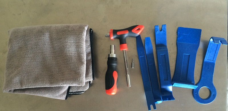
I don't have time now to go much further with the project, so I'll post this as -is for now. Anyone wanting to get into the center tunnel might find this useful. In a separate project I will crack-open the box and take a look at the guts.... Let's get started.... For this project, you should have a good set of plastic interior trim tools handy. I had a set that I bought from Harbor Freight for like $10, plus some other tools that I've accumulated over time.
1. My 991 has full leather. The trim pieces are all covered in a black "leather" or material of some sort. Don't think it is leather, but it is a soft black covering matching the interior black leather.
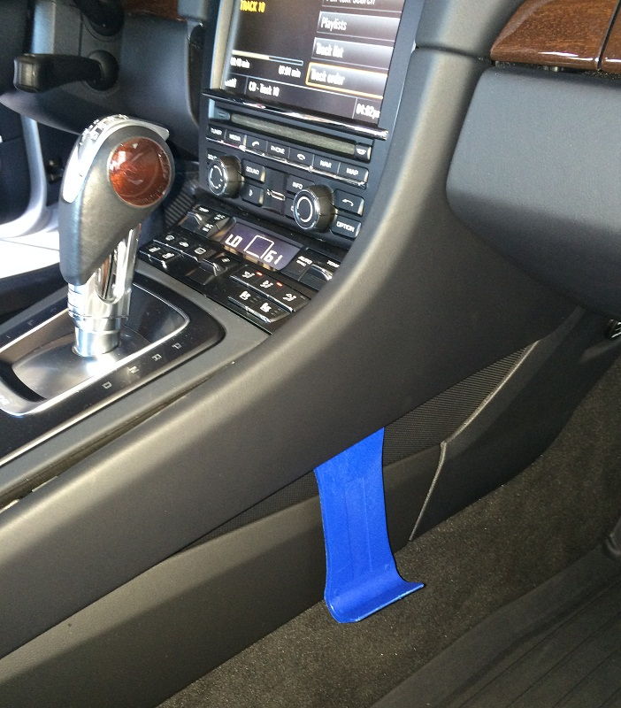
2. Just below where the coin-tray or ashtray is located, you can work a soft tool under the edge and pry-up. Be very careful. The fabric pieces can be dimpled or marked as you apply leverage. I don't have a set of trim tools, so I improvised and used a plastic squeege tool I have from applying films.
3. Prying the end up a bit further to get the sides started....
4. And then working the tool around the length of the trim... The trim is fragile, and I was taking great care not to mark it or "dent". Later you'll see the long prongs that you need to work free to release the trim. Just work up each side to the top above the shift lever.
And
And
5. Gently pull the trim piece off and over the shifter.
6. Here is the trim piece fully removed. Note the long tension prongs around the sides. Don't want to break those off.... Put the piece somewhere safe.
7. Not the best pic, but note the gap around the button and shifter modules. There is a rubber gasket down in the space.
8. Gently pull the rubber gasket out -- in my case I simply pulled it up and back over the shifter but didn't fully remove.
9. With the gasket removed, you now have the sides of the button and shifter modules exposed a bit. These are just held in place by tension -- no screws or other tricks.
10. I started with the button module. It is in there very tight, so you need to be careful but pull on it enough to free the tension tabs -- there are 4 tabs, two on each side. I put a fiber cloth over the unit and pulled up on one side first to get it free. Then it popped-out suddenly!
And...
11. Pull the center unit out of the way, and you have now exposed all of the great space hidden underneath. The unit is a single "box" set for all of the buttons.
12. I pulled the small black "coin-tray" out (just held in place by a couple of tabs) of the way and you can see some of the great stuff inside. Like the white and chrome cylinder thingy -- a linkage to the PDK shifter. Bunch of other wires, but a lot less cluttered than I thought it would be!
13. Flipping the button-box over, you will find that there is a single, thin gang of 5 or so wires attaching the box to the car via a small white plastic connector. Easy enough to pull out! But also note on the underside is a sticker with several part numbers. I am guessing the part numbers correspond to the optional buttons that I have included in my build -- I do not have PSE, so I am thinking the numbers must be Sport Chrono, but not sure what else. I did a quick Google of the part number, but got nuthin'! Anyone have a part manual around??? Anyone know what the "DML" designation stands-for after each number? (UPDATE: My friends on 6SpeedOnline have informed me that the DML code is for the "Black interior" on my particular car.
The numbers at the bottom of the sticker may be the Software (SW) and Hardware (HW) rev numbers for the unit. There is also a date, 05/27/2013 which I am assuming is the date the unit came of the bench or configured for my install. My 991 build date was 06/2013, so that sounds right.
Anyways -- that is it for now. I don't have the time to pull the rest apart. I've posted another DIY project (PCM 3.1 removal) where the center console trim must be removed, and soon I will post a project where I take apart the actual console switch box assembly! Hope this helps someone!
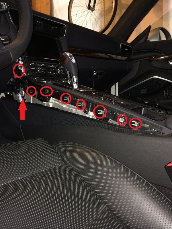
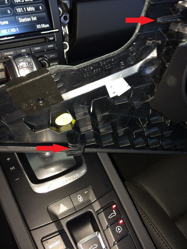
(originally posted on 6speedonline.com 8/30/2014) This is the second part DIY for removing the PCM 3.1 unit from the dash of a '14 991 C4S. Visit Part 1 if you need to remove the right and left side trim pieces.... In previous steps, we've removed the two console trim pieces. Here I've indicated all of the female receptacles in the console that the trim piece connects-to:
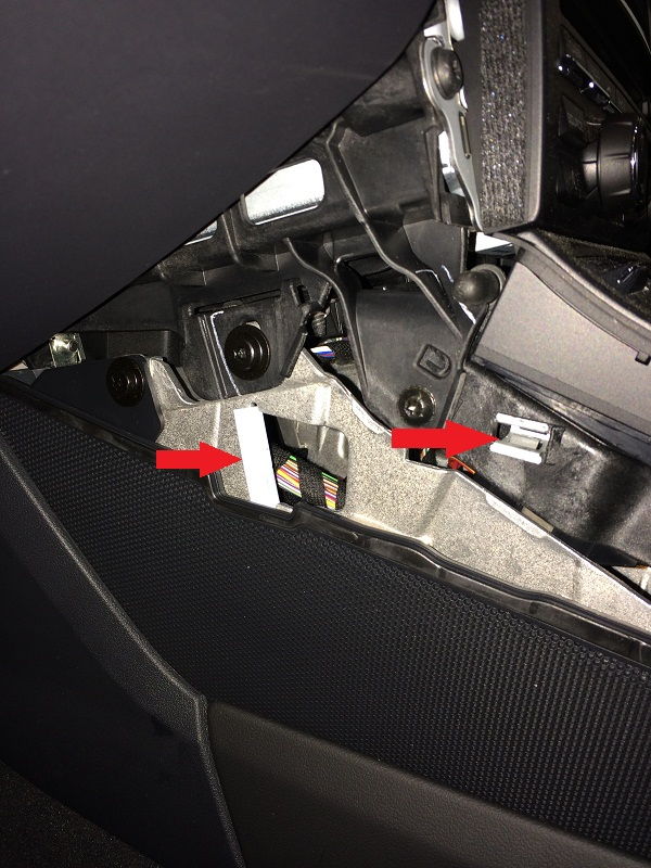
In this pic I indicate the slot where the "hook-tab" connects - you don't want to break this one off (see further down for a pic of the tab)!
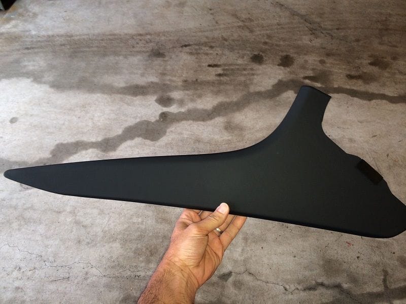
Here's a pic of the passenger side trim piece removed:
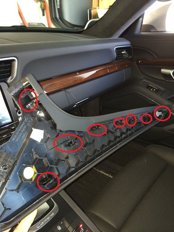
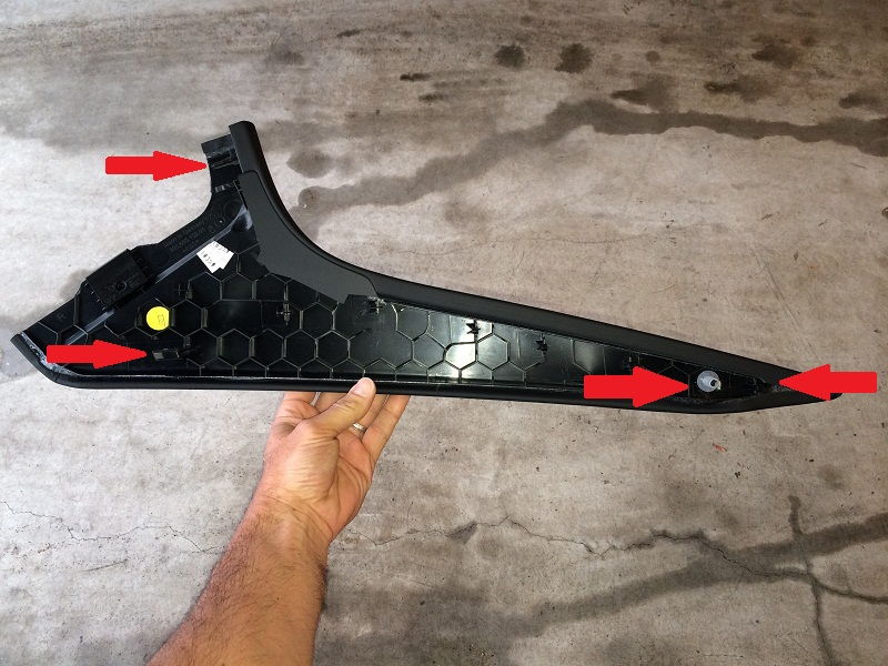
And in these shots I circled all the little tension tabs on the reverse side of each piece. There are a lot of them!
There is one tab that is really fragile, and it is more of a "hook" tab that has to clamp into its' connection point under the dash - here is a pic highlighting this tab... Also, note at the top there is a tab that simply insert straight-ahead into the console next to the PCM unit in the dash.
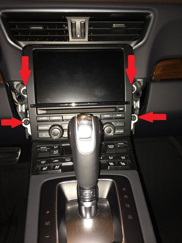
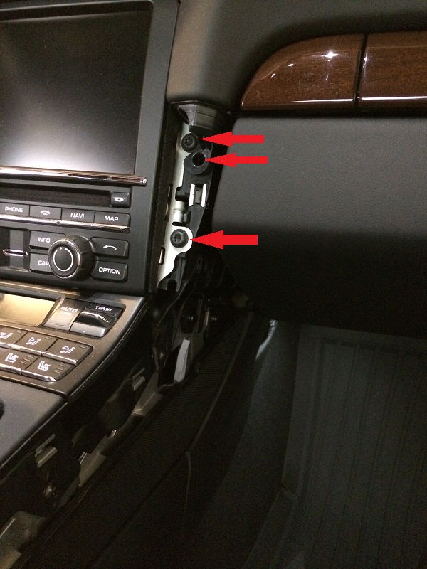
With the trim panels removed, you have now exposed the PCM unit screws to each side of the PCM unit. Indicated in this pic are the 4 T-25 screws that you need to remove from the PCM unit to get it out of the dash:
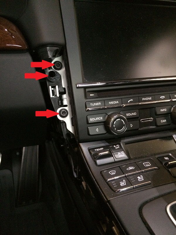
And here are close-ups of the right / left side screws (I also indicate the hole where one of the trim piece tabs inserts straight-forward)
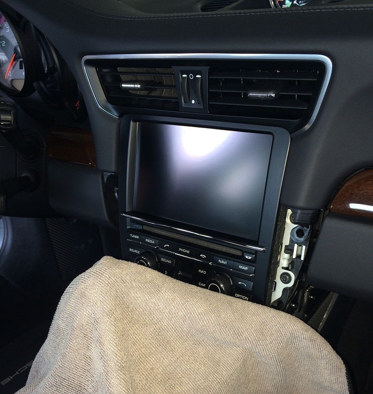
Cover the area directly below the PCM unit, and move the gear selector back
Remove the screws...
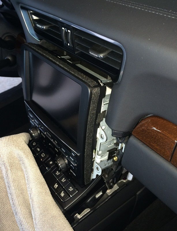
Gently pull the unit out of the dash
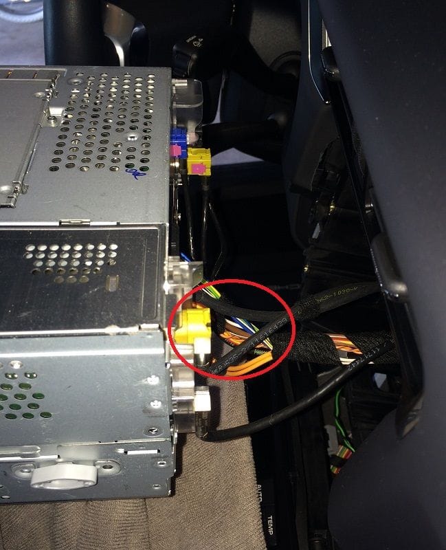
When you have the unit out far enough to reach the cables in the rear of the unit, you will want to disconnect everything. Be CAREFUL how you remove the connectors -- if you pull too hard on the wires you can pull them out of the connector module! So gently work the connectors out.
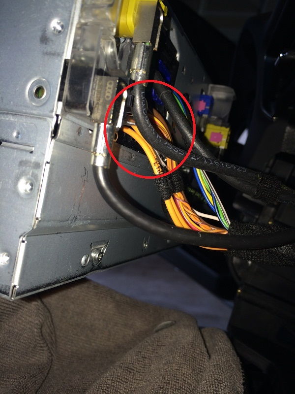
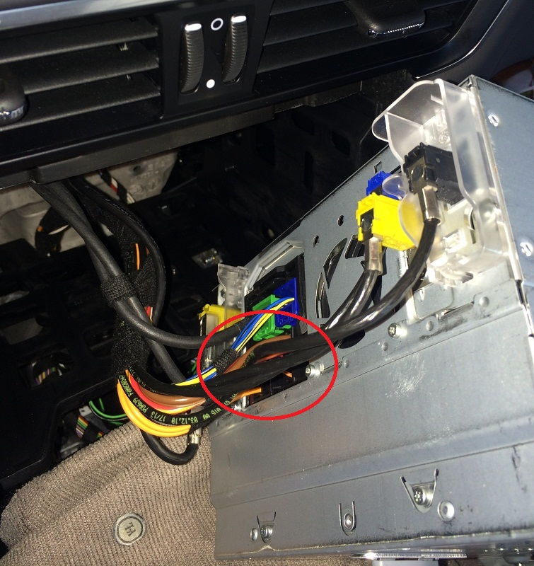
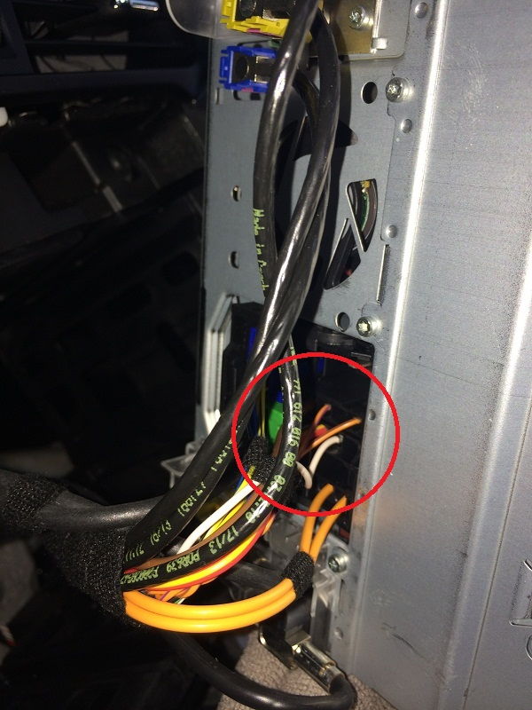
Here are some pics of the rear of the PCM unit (I've circled the wire bundle that you want to focus-on for integrating something like the NAV-TV plug-and-play harness....)
If you are adding a different NAV-TV connector, like the RGB3.1 or the AV970 kits, you will have to remove the unit entirely so that you can put it on a bench and open the case. Unless you have to I would avoid breaking the warranty seals on the unit until after warranty period ends. You don't want any problems you have before then to be blamed on your modification!
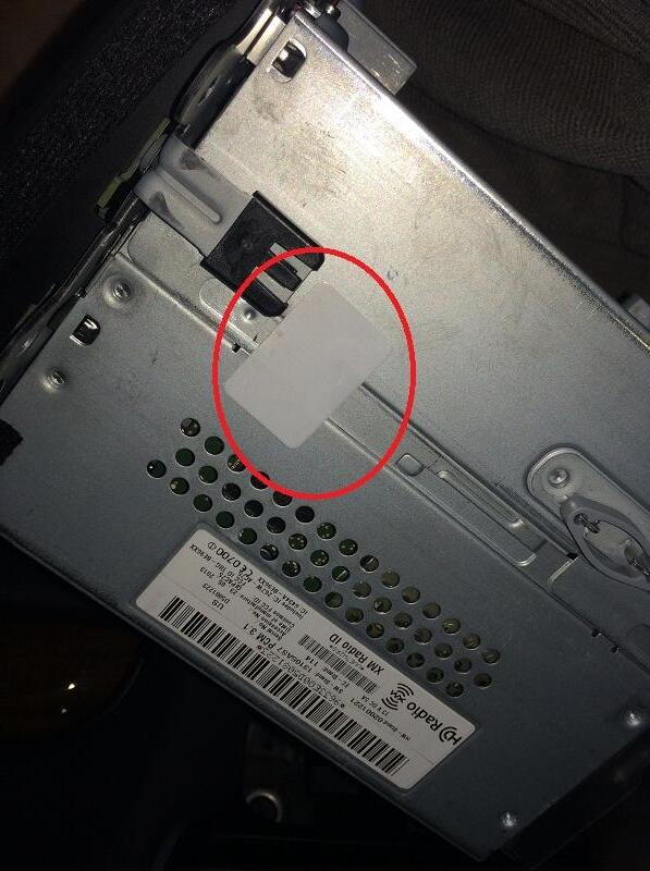
Interestingly, I was expecting a large warning label about voiding warranty, but all I found was this little white label...
That's it for now! I don't have the NAV-TV unit yet to actually connect everything, but I will soon and will put together another DIY showing the process of making the connections, and wiring-up a camera from the rear. To put everything back the way it was, simply reverse the steps above!
(originally posted on 6speedonline.com 8/30/2014) Objective of this DIY is to remove the PCM "head unit" and touch-screen from the dash of my 2014 Porsche 911 Carrera 4S. Consider this a prep project for a Rear Video Camera install DIY (see other posts), as these are the steps you will need to follow to install an interface like the NAV-TV PCM3.1XG-CAM video source. Actually, you would need to follow these steps for just about ANY installation requiring interface with the PCM dash unit! (If you want to simply skip to the end where there are pics of the rear of the PCM unit / wiring,Go To Part 2.) The entire process of removing 2 trim pieces and screws holding the PCM unit in place took approx 30 minutes -- a lot less if you aren't stopping to take pictures! First time you remove the trim pieces go slow, take your time... First, make sure you have the following tools ready:
T-25 Torx
Nylon / Plastic Interior Trim Tools
Soft towel or other cloth (you will want to cover the console / shifter area when you pull the PCM head unit out of the dash)
NOTE: Although you'll notice my unit has power during the DIY, I would recommend that you disconnect battery / power so that you don't run into any electrical "issues" while pulling the unit out. Also make sure you are grounding occasionally to something metal, not just the PCM housing....
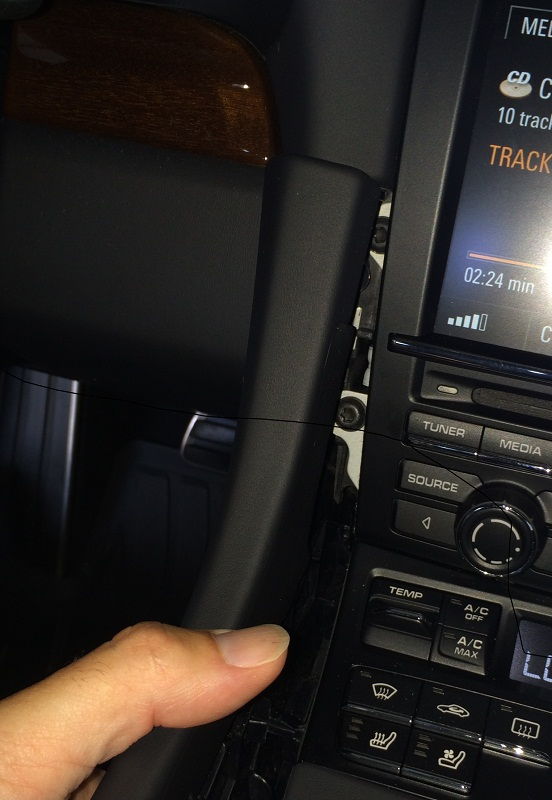
First, put your seats as far back as they'll go, put on some good tunes, and start to remove the trim panels on each side of the center tunnel. These pieces in my case are covered in leather, so I was very careful not to do anything to scratch them.
Also note that these pieces can also be tricky to remove. DON'T be too forceful and simply yank it off, as there are a couple of tabs/pins that can break-off. Once that happens I don't think there is much you can do to fix, and you may end-up with a squeaky center console or something!
Let's get started!
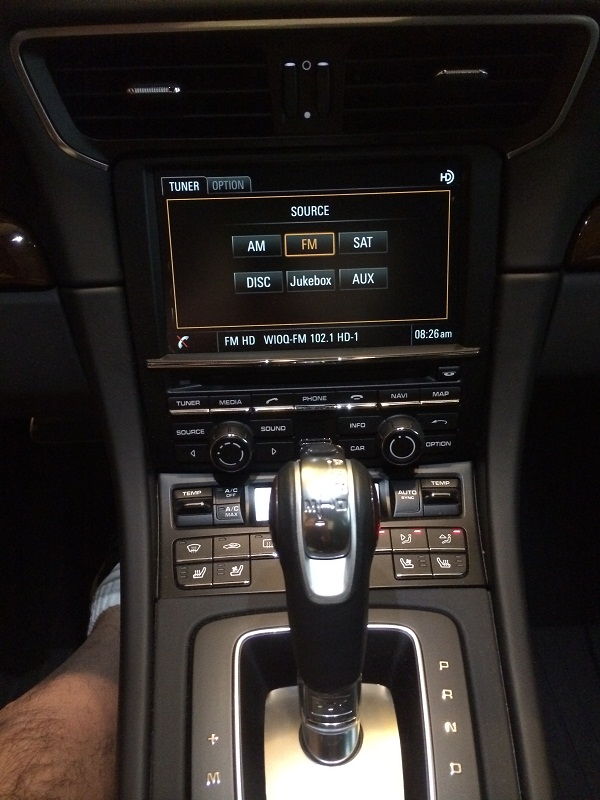
Here's a pic of the console area in my car. On my '14 C4S I've got leather surfaces and PDK. You may find it easier to pull the PCM unit out if you move the gear selector back, but you don't have to.... if you are very careful and have small hands!
Another pic of the area
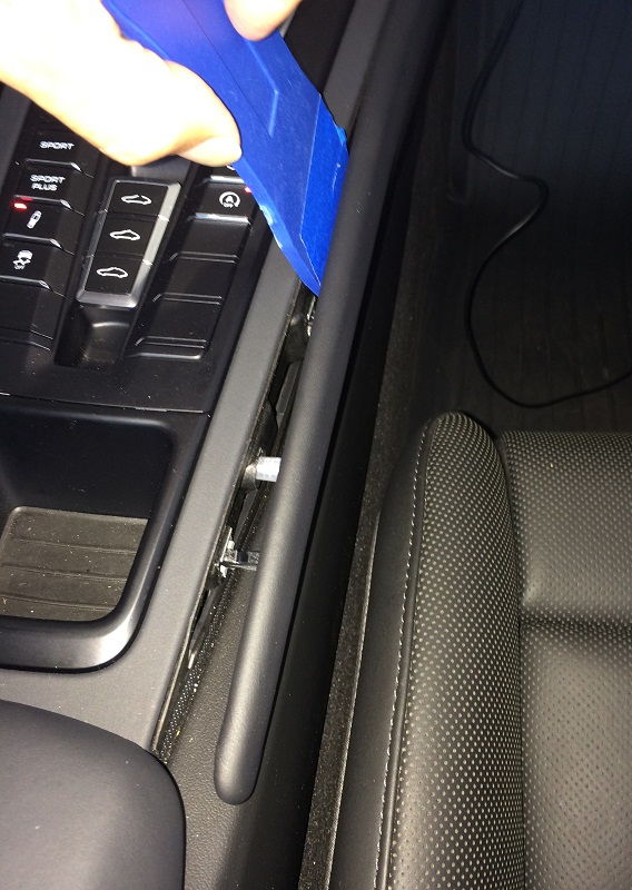
Start at the smaller, pointed end near the center console storage bin, and carefully work the tension tabs out of each connection point moving towards the dash. Using the trim tools is a huge help. I found that wedging behind the trim and gently pushing out away from the console worked well, and for the last tab close to the dash putting the tool in from the bottom and pushing out while pulling towards me helped a lot!
I started on the left, or driver's side...
You need to be very careful not to just yank the panel straight-out away from console, as there is a hook-tab that is very easy to snap-off if you don't work it backwards out of it's retaining hole first....
And here I am pulling the right or passenger side trim off...
On the passenger side, you can lower the glove box door to give yourself a bit more wiggle-room to work the trim panel off...
Here are a pics of the trim piece removed from various angles (both sides)
You now have the two trim pieces off, and can move on to removing the PCM unit from the dash.


 If you'd like to see a video of the blinking upper brake light in action, jump to the bottom of this post for a link to my YouTube channel GTSilver....