Showing posts with label C2S. Show all posts

Friday, June 10, 2016

Porsche 991 Interior Trim: Fuse Panel Trim Removal

UPDATE:  Adding pictures and some additional description of the parts and how they connect to the car...  Many thanks to Rennlist member RoWa for the additional material!

Trying to help-out a fellow 991 owner...  I was asked about how the footwell trim piece that surrounds the fuse panel attaches.  Apparently the owner has a loose trim piece and although can feel that there is a connection point loose, isn't sure how to repair.

Here is a parts diagram showing the parts:


In particular, we are focused on parts identified in this diagram as #'s 5, 6, 7, and 8.

Part #'s and descriptions  (always check your part #'s with your service dept or someplace online like SunCoast, as I've now seen couple of different #'s for the following):

(5) 991 555 101 01  Lining Fusebox (you need to add your color code for interior color, which for example in my case is black, or A75)

(6) 999 507 533 02 Clamp
(7) 999 507 533 01 Spring Clamp

(8)  991 555 622 02 Lid Lining Fusebox
Again, for each of the colored parts you will need to indicate your interior color code.  Additionally, in this case there are both Right and Left-side parts, so you'll also need to indicate /R  /L with part # as they don't have separate #'s.

Thanks to Rennlist member RoWa, we now know that in fact the trim panel surrounding the fuse box is secured to the car with a number of small tabs and velcro.  Per RoWa....
"The left side has fairly standard trim mounts. The right side is secured with 2 two-sided velcro-like fastners. One side of the velco fastner is mounted on the frame of the car, the other side, mounted on a circular plastic disc, is attached to the fuse panel trim. These discs, mounted on the fuse panel trim, are removable from it - they just pop off."
Following are some pics RoWa provides to help understand how the part attaches.  NOTE that in this case all parts are from the driver's-side footwell panel.  Referring to right vs left side of part means closer to door vs closer to footrest.  Assume on right-hand side of car the part is simply reversed.
Entire trim piece with door attached  viewed from behind, noting connection points on both sides.
Closer look at the "left-side" connectors w/velcro.

So in the case where the (5) trim lining the fusebox appears "loose" or has come-off, you'll want to focus on the connection points indicated above.


Friday, March 4, 2016

Porsche 991 Vinyl Hood Wrap Removal

The other day I removed the 3M vinyl wrap from the hood of my 2014 991 C4S...  Created a short, "fast-forward" video for my YouTube channel (GTSilver - Please follow!).


As always, Thank You to everyone for their support!  Please comment below, and for more pictures, videos, and other stuff subscribe to my Twitter feed @GTSilver991!

Monday, February 8, 2016

Porsche 991.1 Plastidip Removal from Mirrors


I've had the mirrors on my GT Silver 2014 991 C4S sprayed in Plastidip Matte Black for the past year or so.  Decided to remove the 'dip as I am preparing for other projects.  To remove the dip I wanted to remove the mirrors entirely from the doors.  Thought I'd show you the process of removing the mirrors from the doors.  Might be useful for anyone wanting to send their mirrors out for painting, or wrapping, as well as for those who might want to swap their mirrors for another set....

Couple of things to note....  I have the standard 991 mirrors.  I do NOT have the power folding, Sport Design, or "GT3" mirrors.  However, I believe in any case the procedure to remove the mirror from the door is the same -- remove trim, a single bolt, and pull the wiring harness through the door.

Also, when I bought the car, the dealer had already installed xPEL PPF, and there are small pieces on the mirrors.  When I sprayed with Plastidip, I just sprayed right over the film.  So, I really wasn't sure if the 'dip was going to bond or "merge" and stain the clear film.  But actually what I found is that the 'dip spray peeled-off more easily from where the film was than where it was not!  As you can see in the video I shot, the 'dip peels off real easily from the mirrors.  Each mirror took me about 30 minutes to peel and clean-up.  Where I had difficulty peeling, I simply brushed on some Xylene and wiped the 'dip off!  Very easy!

I continue to be impressed by the durability and versatility of Plastidip!  It is amazing stuff.  My car is no garage queen, so seeing first-hand how it protects the car I am a true believer!

Here's the video posted up on my YouTube Channel - GTSilver....  Please subscribe for more!


Tuesday, January 12, 2016

DIY: Porsche 991 911 C4S Inner Door Panel Removal and Installation

Hi All-

I've put together a YouTube video showing how to remove the full inner-door panel of my 2014 991 C4S.  The procedure for ALL 991 model years and configurations is the same, and I believe this also applies to the 981 platform as well.

I had to add narration after the video was shot -- too much background noise at the time made it hard to record.  If you need additional guidance, let me know.  I also have step-by-step written instructions.

The procedure is really quite simple, and even for the novice is very low-risk and you should be able to get the full panel off within 10-15 minutes using this video...

Enjoy!

Porsche 911 991 C4S Inner Door Panel Removal & Installation


Wednesday, May 6, 2015

991 DIY: Removing / Installing Front 3-Point Seat Belts

Following is a brief DIY for those of you out there who want to swap their factory three-point seat belts for different color, need to remove the seat belts for another project, replacement after an accident, etc.  I don't have any pictures at this time, sorry.  This will have to be purely a description DIY until I can find some time to do this on my own C4S.

Let's go!

Preparation:

  • You will need to have an assortment of Hex and Torx bits, sockets and a screwdriver available.  I don't have all of the individual sizes available at the moment.
  • Have a set of plastic interior trim tools handy.  You will need to remove the trim covering the belt assemblies, etc.
  • Disconnect the negative (-) terminal to the battery!  You must do this to avoid any issues with the pretensioner unit, either triggering or throwing fault codes.  Also remove the key from the ignition (if you have keyless entry, remove the starter key from the dash).  I have read various opinions on whether this is necessary on the modern P-cars or not, but why take the risk?  The official PAG Workshop Manual (WM 691119) instructs the disconnection of the battery, so I say do it!
Note:  The seat belt pretensioner unit is no longer usable or safe once it is triggered.  The unit triggers an explosive charge to lock the belt when there is an accident, and should then be replaced.  It works in conjunction with the Airbag (except in rear-ender where the airbags won't fire.)  If you need a replacement, you can order from authorized Porsche parts suppliers.

  • Lastly, You are going to be working in some tight spaces.  Consider whether it would be a whole lot easier for you if you remove the front seats entirely from the car.  Totally something even the newbie DIY can tackle, and will make your life a lot easier.

Step 1: Remove B-Pillar Trim

  • Loosen the three-point set belt bolt found at the bottom near the door sill.  There is a small black plastic cap covering the bolt.
  • Using a trim tool or your fingers, grip the belt "collar" trim piece on the B-Pillar on the sides and pull directly out from the pillar. 
  • Release the unlocking bracket on the clamps and pull it forward.
    • You may need to use a pointy tool or wire hangar bent to release from within the pillar...
  • Slide the trim piece down the belt out of the way (exposing the seat belt mounting points which were concealed by the trim piece).

Step 2:  Remove the Rear Side Panel Trim

  • You may want to remove the C-Pillar trim piece (upper trim piece where the rear seatbelt enters the roof-line belt collar - and you will need to remove this piece if you are replacing the rear seat belts...) first.  The trim pieces for the side panel, roof panel, and C-panel all come together back there, and it may be less risky to remove the C-pillar trim first.
  • Remove the rear seat cushions -- you can just lift up and pull forwards.
  • Unscrew the rear seat back locking pins from the side panel -- using a socket or drill with appropriate bit ( I believe this is a T25 bit), unscrew the locking pin and place aside.  This is the only fastener holding the panel in place.
  • Grabbing the side panel trim at the bottom and top, pull the side trim panel up and swivel it inwards from the top towards you.
  • Disconnect the electric connector to the side panel speaker
  • Pull the backrest bearing collar inwards and off.

Step 3:  Unfasten Front Seat Belt Mounts

  • By the door sill, locate the lower mounting point of the front seat belt, which you loosened previously.  There is a plastic cap over the bolt --  remove the protective cap.
  • Using an appropriate Torx, unscrew fastening screw and remove belt fitting and spacer sleeve.
  • At top of the belt, at the B-Pillar, use your Torx to unscrew and remove fastening screw.
  • Pull the belt strap out of the guide bar.

Step 4:  Remove Seat Belt Pretensioner Unit

  • Moving down the B-Pillar, locate the Pretensioner unit.
  • There is a single fastener holding the pretensioner unit to the pillar.
  • Using your Torx, unscrew the fastener.
  • Pull the pretensioner unit up and out of the pillar.
NOTE there are electrical connection(s) to the pretensioner!  There are variants, based on geographic region.  Following is for USA.  Rest of world there is only a single electrical connection -- I can't confirm this, but if you find one or more connectors, they all work the same way.
  • Release the locks on the electric connectors (USA) on the seat belt pretensioner using a screwdriver.
  • Disconnect connectors
And you now should have the entire seat belt assembly removed from the car.  Carefully wrap the removed / stock pretensioners and seat belts and store someplace safe -- or if the pretensioners have already been triggered slice the belt and toss since like an airbag, the pretensioners shouldn't be reused once triggered.

To install new belts and pretensioners, follow the above steps in reverse order.  Also, note that when hanging the new belts, you will want to "turn" the lower mounting plate of the belt 180 degrees before fastening-down.  

If you are tackling this project and take some pictures, I would be happy to post them and give you photo credits!  I think some pictures of the pretensioner, trim panels removed of that area would be very helpful to others!


Monday, March 16, 2015

Porsche 991 911 Center Console Switch Box Deconstruction

Porsche 991 911 Center Console Switch Unit
Here's another one for all fellow "tinkerers" out there...  I have been thinking about how the 991 center console switches function, and what one might be able to do with the "blanks" that all of the 991 models seem to have (I have seen fewer blanks on a GT3, but nearly all other 991 models have at least 3 blanks in the console switch unit).

What follows is a step-by-step breakdown of the center console switch module from a 991.  In this particular case, the donor did not have PSE (Thanks for fellow member for donating!).

My thinking is this... that although the unit is a single controller, we should be able to figure-out how to modify the switches in order to do something with the blank spots, such as build-in custom switches for radar, other accessories that one might want to install.

The challenge in doing anything with this console module?  It is a single control board, with various switches mapped and likely programmed specific to the car and its' options (ie when you add PSE they replace the entire switch unit, not just add a single switch).

In the "old days" you could pull a single, isolated switch from the dash or console, and replace with something else, or at least gain direct access to specific wires and such going to the accessory buttons.  Nowadays, all of the switches are on a single circuit board, and tie-in to the car network (CAN) through a couple of wires and a connector.  So you really can't just move the switches around, remove something and replace with a different function, etc.  At least not yet...  LOL

Let's get to the deconstruction.

You need to remove the switch module from the center console, so if you haven't already you should review the DIY I posted previously on just how to do this.


So if you've followed the removal DIY, disconnected the cable running to the switch-box, you should be holding the 'black box' at this point.  Here is the module sitting on my bench...

This is the "underside" of the switch box.
Note the part #'s S/W and H/W versions
After you have the module on your bench, flip it over so you are looking at the "bottom."

There are 6 torx head screws that you need to remove, as indicated in the following picture.

The small screws removed....
Using the smallest T bit that I have I removed each one and set aside...  These are small, so if you have a tray or even a small plastic sandwich bag you should put them in a safe place.  Would hate to lose one of these buggers!

With the screws removed, gently pull-up on the the back-cover and put aside.  You'll find as you separate the back from the main assembly that there is a rubber gasket layer sandwiched in there (covering the circuit board) - you'll notice it in the area where my thumb is in the following pic.


Place the back cover aside.  In this picture, you can see what you've exposed is a single circuit board.


Now pull-up gently on the circuit board, separating it from the main assembly.  Do so carefully, as in the picture below you'll find that there is a spring in the center -- don't lose that!

Red arrow indicates a small spring in the center of the assembly.
Have something handy, like a small bowl or plastic bag, to put the small bits in.  Place the circuit board to the side.


Since the "top" of the switch box assembly is face-down on your table, you are now looking at the underside of the switch actuators....

I've indicated where the "blanks" are so you can see the difference
between those and the actual "live" switches from the console...
The first observation about this is that given the space under the dummy switch covers (effectively they are hollow) it is very possible that an aftermarket / custom switch assembly can be added.  More on that later.

Let's move over to the circuit board for a moment....


On one side you see the standard green board with some chips and other bits visible.  Flip it over and on the other side is a rubber gasket of sorts...  You can pull that off - there isn't anything holding it in place that you need to worry about.


The small metal discs correspond to the switch contact points, which in turn are mapped to the corresponding circuits for controlling specific features / functions of the car.  This is all via CAN-BUS and programming, so if you were expecting to be able to tap into specific wiring for a switch you are out of luck!  These are pressure sensitive contact points, and represent either an ON or OFF state....  The rubber gasket is effectively protecting the circuit board and contacts from any moisture, such as when someone might spill or drip beverages onto the center console.  Might make for some sticky buttons, but looks to me like there wouldn't be much chance for shorting or other electrical problems!

Back at the "rear" of the switch console box -- you can remove the three grey assemblies, taking care with the center one which has a spring.  The plastic bits literally just fall-out so nothing tricky needed for removal.


In the case of my car the switch buttons are to control the metal sunroof.  Open / Close / Partial settings and corresponding buttons.  If this were a cab car, I would expect these buttons to control the top open / close functions.  In a coupe with NO sunroof option?  Not sure what would be there. Probably just blanks.

To remove one of the buttons that are already in place, you will need to push it out from the rear.  I used a small micro-screwdriver and gently pushed until it popped-out a bit and I could pull it the rest of the way out.


Here's a pic of the switch face plate or cover removed...


The face plate is a small thin black plastic part with a small hole in the corner (for the red indicator light).  NOTE that the face plates are right - or - left side specific.  For example, the PSE button can only be installed to the right bank of buttons...


Once you have the switch face plate removed, you can remove the chrome plastic bit from the front of the console box.

In the following picture, you can see the "dummy" or blank button face removed, with the small chrome bit removed from the "real" button just above.


Here you can see the difference in a "dummy" button  (circled in red) and "real" or working button (upper space in the pic below) when the faces of the two buttons are removed.  In the functioning button, note there is a black "box" of sorts inserted, which when face is on and pressed contacts with the actual contact switch on the circuit board.


You can remove the black plastic "box" in a switch by gently pressing on it from the face side to push it out the back of the console box.  And do the reverse if you are inserting a new button....


Following is a pic showing the two buttons on the right that have been completely removed from the switch box.

And from the reverse side....


Pic of the various bits deconstructed and laid-out on the bench.


So, you've deconstructed your center console switch box...  What can we do with this information???

Well, I didn't do anything.  I simply put it all back together again.  But, I now know that if I really wanted to add a "custom" switch integrated to look factory installed I could.  It isn't going to be fully-integrated at an electronics communication level (CAN BUS), but a physical integration with the switch face plates.  To add a custom switch, you will have to create an access port into the space directly under the switch face plate you are customizing.  This means drilling a small hole on the side of the console box and routing your wiring through and into the space directly below the switch box.

Of course, until someone does this and shows in detail, it is just a concept.  Couple of other things to know -- You can purchase a switch repair kit from Porsche that includes replacement switch face plates, switch console box, and other bits.  I think this currently runs about US $225 or so.  Also, this kit is needed whenever an owner adds Porsche Sports Exhaust to their car, as the kit includes the new button to turn the PSE on and off.  Here is a pic of the kit (swiped this from an online marketplace):


Note also that the switch repair kit does require a match to your VIN -- in the example pic above, this kit was obviously for a car that is NOT a convertible, and doesn't include the metal or glass sunroof option, since there are no buttons for roof control in the middle of the switch panel.  So check your VIN when you order a switch repair kit.  And no, getting a kit with the additional buttons DOES NOT mean that by installing you will magically have PDCC, front lift kit, PSE, or a convertible!!!!  LOL.  These are replacement buttons and other parts, but you will need to get any programming done by the dealer (or independent with the PIWIS tool and the option codes for your car from the factory).

Anyways, this is a LONG post -- sorry all!  I've run out of steam.  Happy to answer any questions if you want to post them.  I also have a spare switch kit that I can dig into in more detail if you have any questions.

Thanks!

Sunday, March 1, 2015

PCA Club Coupe Edition 991

Attended PCA Tech Tactics East Saturday Feb 28th.  I'll post other material from the event, but focus in this post on the special 991 Porsche created for Porsche Club of America's 60th Anniversary...

First, a disclaimer:  I took the pictures with an iPhone, which is bad enough -- but on top of that, the lighting conditions in the space where the car was located were just awful.  The area was a very clean service bay/training room in the PCNA facilities, but there were large windows on one side close to the car and a lot of sunlight was coming through.  So needless to say, some of the pictures came out quite crummy.  Oh well...

The car was revealed to the attendees as a 'surprise' -- it was hidden in an adjoining training facility, and at the proper moment on queue a large garage door opened and there it was!  This is apparently the first and only 991 Club Coupe edition at this time.

The car is quite beautiful.  I think they came up with a great color which is special for PCA -- Porsche AG officially named it 'club blau'.  This color is only available at the moment on the Club Coupe.  It was mentioned during the meeting that the color may be available in about 2 model years for PTS orders.  It was also interesting to hear about the process to create this special car.  Apparently took about two years, and PCA didn't know that the Club Coupe would be based upon a GTS until the GTS model was unvield.

In person, the color is both very bold and "muted" at the same time.  Kind of like a monochrome color but with a very shiny gloss to it.  It isn't neon, and not in-your-face metallic.  But it is a stand-out in a sea of white, silver, black, red spectrum colored cars on the road....  This blue is flat but not matte or "frozen".  As you can see in the following pics the tone is lighter in bright lighting and looks much darker in shade or darker lighting conditions.  Very cool.

Just a few other notes before we get to the pics....  What makes this car special is the color and a few styling bits.  Beyond that, the car is like a GTS.  The interior is nearly identical to my own 991 C4S, but for a red centering indicator stripe on the steering wheel....  I didn't take any pics of the interior for the simple fact that it wasn't anything special.

On the outside, aside from the color and the 50th model wheels, the only other visual was a small decal on the lower front of each door indicating "Club Coupe."  My personal opinion - they should have changed the rear badging to reflect the special edition -- but they left it as the normal GTS badging.

So here are the pics:


Notice the 'orange peel' in the door paint??!


One final note:  PCNA will be giving away (NOT a raffle) one of the 60 Club Coupe cars to a very lucky PCA member!  All active members will be eligible for the drawing, so make sure your PCA membership is paid up!  They didn't explain when the drawing would be however, so stay tuned to your PCA newsletter for the details.

Friday, January 23, 2015

DIY - Porsche 991 911 Side Mirror Removal

(UPDATED:  Added my YouTube video)

Following is a DIY on how to remove the exterior side mirrors from the 991 doors. In my case I have a '14 991 C4S with standard mirrors (NOT Sport Design/GT3 style). I also don't have the power folding option. Not sure how much different the removal steps would be other than perhaps additional wires in the harness...


As I started this project, I was amazed at just how easy it is to get to the single bolt holding the mirror to the door!

Tools required:
  • Torx T-40 with long / extension bar
  • Interior Panel Tools

SAFETY: You shouldn't have anything to worry about with this little DIY, but CYA you can disconnect the negative (-) terminal connection on your battery to be sure that the side door airbag doesn't trigger.... This is a very very remote possibility in this case -- I would be more concerned with this if I were removing the entire door panel!

SHORTCUT:  If you would rather see someone doing the DIY, rather than describing it, check out my YouTube video:


You may also want to put down some towels, other bits to protect any surfaces you are worried about. As always, just take your time, don't force anything (unnecessarily!), and you shouldn't have any worries.

SORRY for the shadows and some blurry pics! car was partially in the sun in my garage, and I was holding my iPhone with one hand.... 

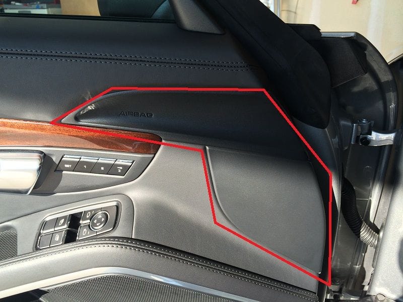
Step 1: Open the door. At the front edge, there are what appear to be two plastic panels - they are actually one large panel - where you see "Airbag". In this pic I've indicated the panel.

Click the image to open in full size.

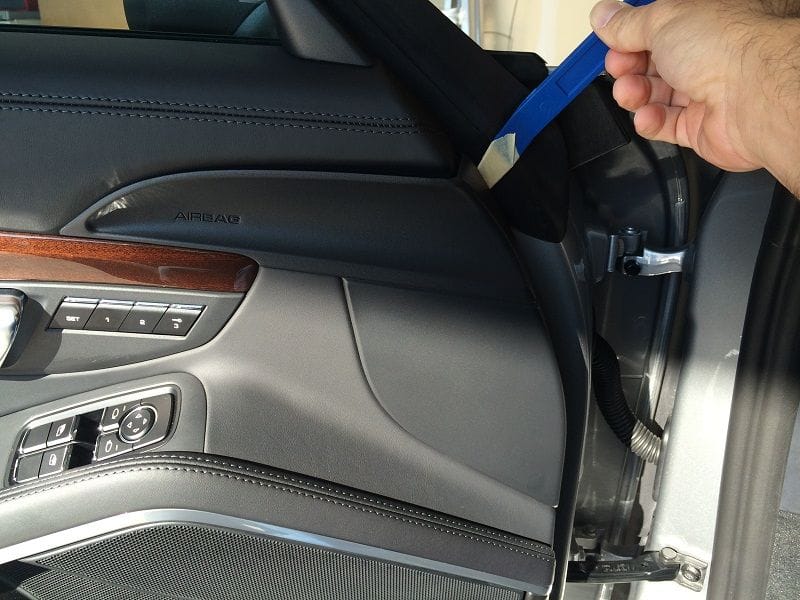
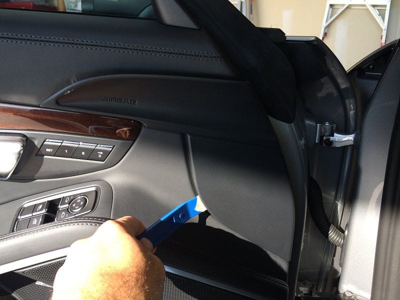
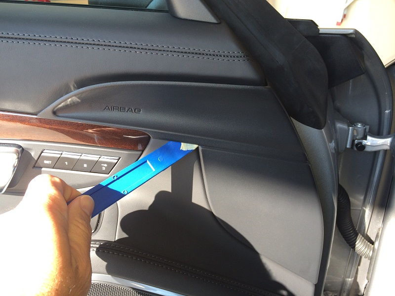
Step 2: Remove the Plastic Panel. Get one of your panel tools -- you could probably do this with your hands only, but I found the tools to be a safe way to go. Start where you see in the picture below, slide your tool edge under the plastic edge where it meets the metal of the door frame, and pry it up from the door. It should "pop" free just a bit.

Click the image to open in full size.

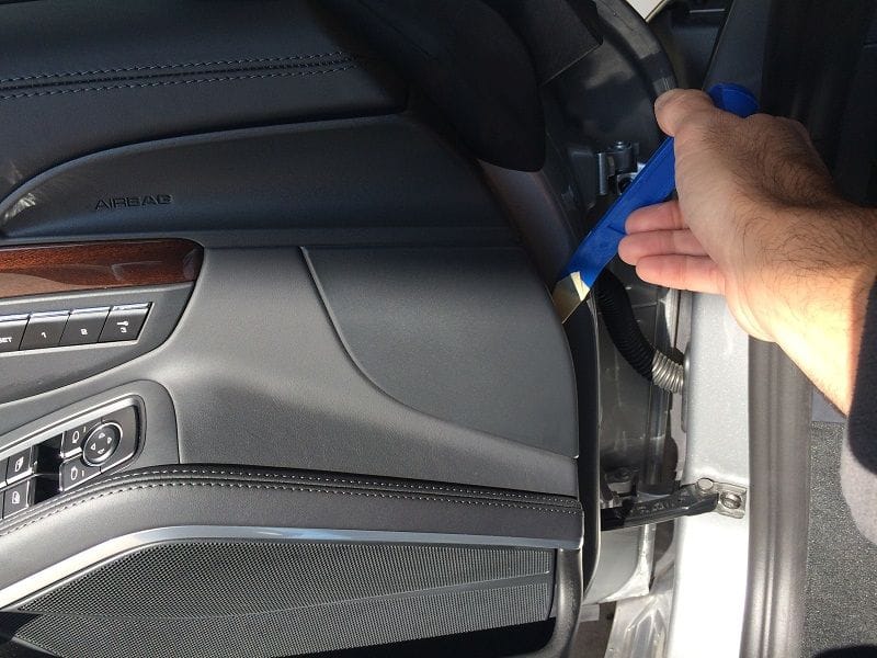
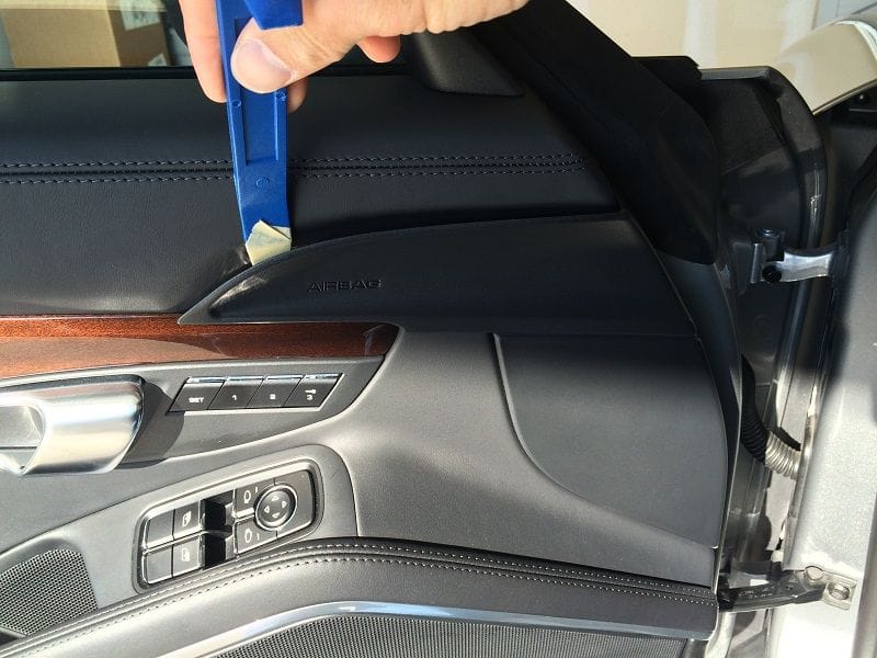
Now follow the pictures in order below to gently pop-free all of the connecting tabs under the panel....

Click the image to open in full size.

Click the image to open in full size.

Click the image to open in full size.

Click the image to open in full size.

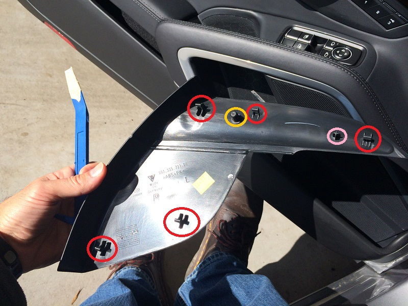
When you get to the last spot around the panel edge, it should just pop-off in your hand. Here is a shot of the rear of the panel, indicating the connecting tabs (red circles).

Click the image to open in full size.

I've also indicated two pins on the rear, in Orange and Pink (what the heck?) circles. These two pins are a bit different, and one has a rubber cover over it that you don't want to lose, or worse, drop in behind the door panel!

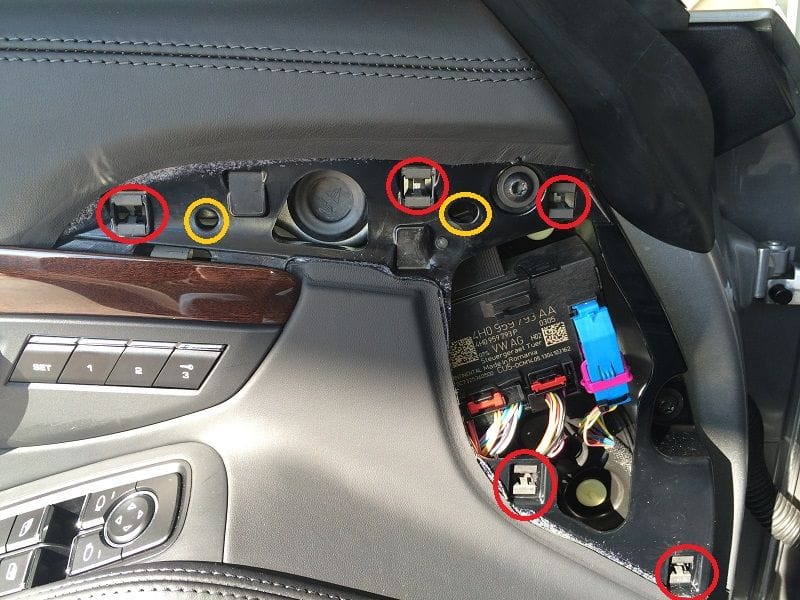
Step 3: Expose Bolt. Now that you have the plastic trim panel removed, look at the door. In the pic below I've first indicated where all the tabs and two pins on the trim piece attach to the door panel...


Click the image to open in full size.

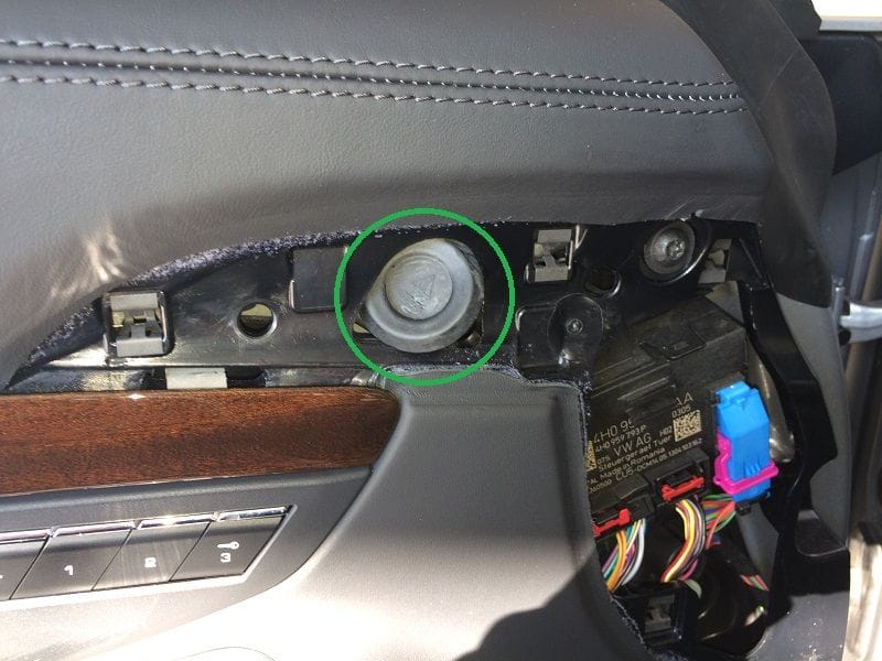
In the center, indicated in this pic, you should see a black rubber plug... circled in green.

Click the image to open in full size.

Directly beneath this plug is the bolt holding the mirror to the door. You want to gently pry the plug up and out of the hole. You can use a thin trim tool or something handy to get one edge up, then just pull it out with your fingers. Don't lose this!

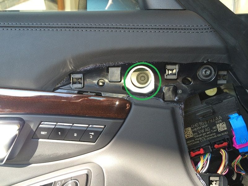
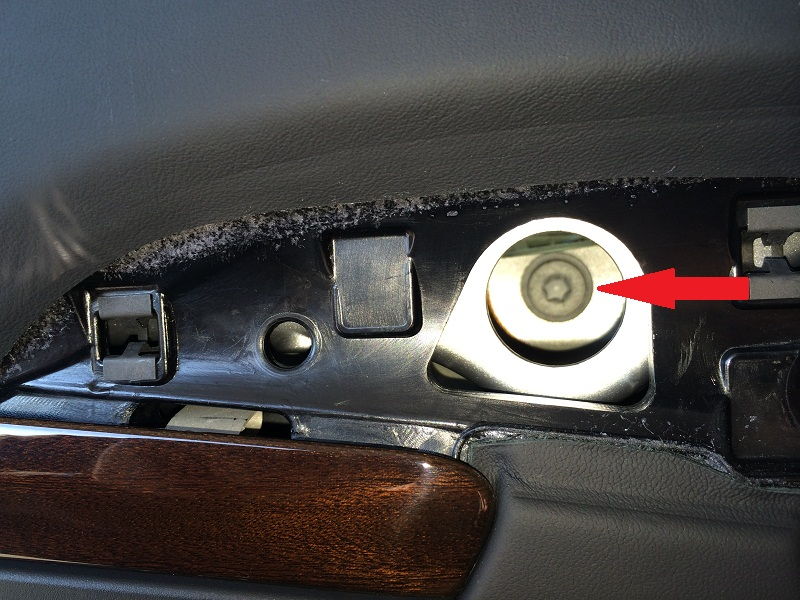
You should now see the opening through which you access the bolt.

Click the image to open in full size.

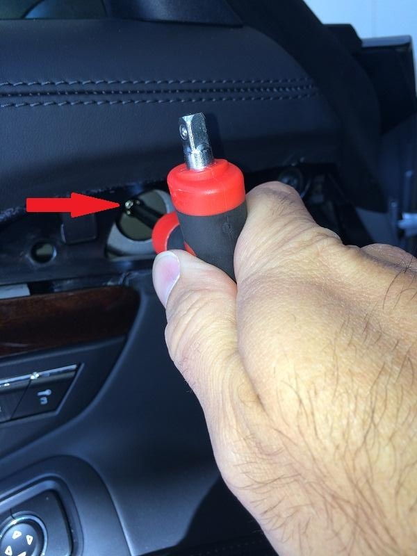
Step 4: Remove the retaining bolt. The bolt is a T-40. You will need an extension of at least 4" or a long handle to reach the bolt. Make sure if you are using a T bit that it is securely held in place in your tool, as you definitely don't want to have it fall out and down into the door! That would suck!

Click the image to open in full size.

Click the image to open in full size.

Before you get the bolt too loose, make sure to put something down on the side of the car to protect the mirror from falling and hitting the side of the car!

Click the image to open in full size.

I found the bolt to be VERY tight. I didn't need a breaker-bar or anything, but took some muscle to loosen. But once I did, the mirror starts releasing from the door as you loosen the bolt.

Click the image to open in full size.

I stopped there. Didn't have time to go any further and take the mirror completely off. I will do that later tonight and post some pics as an edit to this post.

Cheers!

Update:  Some additional details regarding disconnecting the wiring harness so that you can fully remove the mirror from the car...

There is a wiring harness connector that has to be released from the control module that you have to pull out of door when you pull the mirror away from the door surface.  To release the connector, you will have to return to the interior area just below the Airbag trim piece removed previously.

In the following picture, locate the mirror wiring connector in the black control module, just to the left (or right, depending on the door you are facing) of the blue connector -- I've indicated by circling to make it easier....


First, release the electrical connection.  Before you go any further, get a piece of cord, shoelace or similar, and tie one end to the connector that you just released.  You will want this for later, when you need to re-install.

Now, Locate the rubber boot where the wire harness goes through to the outer door shell.  In the pic above I've indicated with red arrows the wire bundle and the rubber boot.  You will have to push it through towards the exterior section of the door, while pulling the mirror up and off the body.  Once you have the mirror far enough out, you can disconnect the wire connector from the cord and leave the cord hanging from the door exterior hole.

The cord will be helpful when you re-install and have to route the wire connector back into the interior door panel.  You should be able to simply tie the end onto the connector and pull it through.  Sorry I don't have a picture of this.

To show you what a mirror looks like when completely removed, I found the following on one of the 991 forums 'for sale' sections.  I've circled the rubber boot and electrical connector for your reference.


Have fun!