Tuesday, June 14, 2016

Porsche 991 Exterior Trim: Rear Diffuser Removal

Recently was asked (within another DIY posting) if there were any guides to removing the diffuser trim pieces from the lower rear of the 991 rear bumper cover....  So I am providing the following DIY guide for those that want to remove the trim parts -- which by default come in matte black plastic from the factory -- for painting, replacement/repair, or to have them custom-painted.

Note that there is an official PCNA Work Manual (WM) for this (WM 636819) procedure, and my guide (along with all illustrations) is based on the instructions provided by that document.

The Porsche official term for the part we are referring to as the diffuser is "rear skirt."  Here is an illustration of the part location:


Rear Diffuser location highlighted in dark blue
There are officially (ie WM 636819) three steps involved:
1) Remove both R and L "Tailpipe Shield Covers";
2) Remove bottom "retaining strip";
3) and, Remove "Rear Skirt".
In the WM the precondition is to remove the entire rear apron (or "bumper cover") but it isn't 100% necessary to do so.... I've seen 991 forum member posts where removal of the "diffuser" happened with the apron still on the car. YMMV.

STEP 1:  Use a flat-head screwdriver or trim tool to release the shield cover by working around the perimeter of the part - I believe there are 5 tabs. You should be able to just pry and pull to release.


STEP 2:  In the second case, and I think personally this is something others have been able to avoid -- there are at least (2) maybe more rivets that the official WM indicates should be "drilled-out" -- meaning they must be replaced if you are reusing the rear skirt parts.


STEP 3:  Remove the rear skirt  by pulling hard while using a screwdriver / pry tool to release the 14 or so tabs that run along the length of the trim piece.


Installation is opposite of the steps outlined here.


Friday, June 10, 2016

Porsche 991 Interior Trim: Fuse Panel Trim Removal

UPDATE:  Adding pictures and some additional description of the parts and how they connect to the car...  Many thanks to Rennlist member RoWa for the additional material!

Trying to help-out a fellow 991 owner...  I was asked about how the footwell trim piece that surrounds the fuse panel attaches.  Apparently the owner has a loose trim piece and although can feel that there is a connection point loose, isn't sure how to repair.

Here is a parts diagram showing the parts:


In particular, we are focused on parts identified in this diagram as #'s 5, 6, 7, and 8.

Part #'s and descriptions  (always check your part #'s with your service dept or someplace online like SunCoast, as I've now seen couple of different #'s for the following):

(5) 991 555 101 01  Lining Fusebox (you need to add your color code for interior color, which for example in my case is black, or A75)

(6) 999 507 533 02 Clamp
(7) 999 507 533 01 Spring Clamp

(8)  991 555 622 02 Lid Lining Fusebox
Again, for each of the colored parts you will need to indicate your interior color code.  Additionally, in this case there are both Right and Left-side parts, so you'll also need to indicate /R  /L with part # as they don't have separate #'s.

Thanks to Rennlist member RoWa, we now know that in fact the trim panel surrounding the fuse box is secured to the car with a number of small tabs and velcro.  Per RoWa....
"The left side has fairly standard trim mounts. The right side is secured with 2 two-sided velcro-like fastners. One side of the velco fastner is mounted on the frame of the car, the other side, mounted on a circular plastic disc, is attached to the fuse panel trim. These discs, mounted on the fuse panel trim, are removable from it - they just pop off."
Following are some pics RoWa provides to help understand how the part attaches.  NOTE that in this case all parts are from the driver's-side footwell panel.  Referring to right vs left side of part means closer to door vs closer to footrest.  Assume on right-hand side of car the part is simply reversed.
Entire trim piece with door attached  viewed from behind, noting connection points on both sides.
Closer look at the "left-side" connectors w/velcro.

So in the case where the (5) trim lining the fusebox appears "loose" or has come-off, you'll want to focus on the connection points indicated above.


Monday, June 6, 2016

Porsche 991 Interior: Removing upper part of centre console cover ­PDK

Just a quick post to help a fellow 991-owner out...  I've previously posted DIY about removing (most) of the center console trim (for the purpose of removing the switch panel, as well as PCM head unit). What I didn't cover was how to remove the 991 PDK shift knob or the trim piece directly around the base of the PDK.

So, without further boring dialog, here goes...
  1. Remove the center console side trim pieces.  You don't need to remove the switch panel directly below the selector trim piece, but you should remove at least the side panels and console trim.  If you do remove the switch panel, it just gives you that much better access to the plug for the hazard light switch and leverage to pull up....  For details, see my other DIY post for center console trim at 2014 Porsche 991 Center Console Trim PanelRemoval

  2. Remove the PDK selector knob.

    • At the base of the PDK selector shaft, there is a locking ring -- turn that to the right. MacCarbon has a decent DIY for replacing the selector knob (with their CF version) and suggest you might need to put some blue masking tape on the ring to gain additional grip.  

    •  Push the knob button at the top forward and pull upwards, releasing it from the selector shaft....

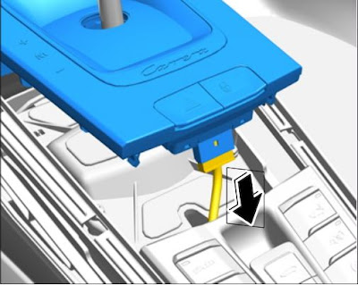
  3. Remove the upper part of center console...  This is the trim around the selector "gate" which includes the model designation label and hazard / locking buttons.  Note that this is a single trim piece and will be lifted-off over the gear selector shaft.

    • Unclip cover by pulling it up ­in the direction of the arrows in this picture:


    • Lift up the cover at the front so that you can easily access the switch connection for the hazard lights;

    • Pull-off the connector for the hazard warning light switch as shown in the picture below:


    • Lift the cover trim piece up and over the selector shaft....
You should now have the trim piece free of the selector shaft, and ready to replace with another piece, etc. Hope this helps!