Latest project in my garage! Check out the video as I demonstrate step-by-step how to remove the front bumper cover on my Porsche 991.1 GTS. The GTS has the sport design front cover, and also has the center radiator. However, removal is the same for any 991.1.
If you have any questions, don't hesitate to comment on the video or contact me directly.
And if you like this and other posts, Please SUBSCRIBE! Please? https://goo.gl/VJghOQ
I posted a video up on my YouTube Channel GTSilver:
Short story is that I was returning home from a "spirited" drive and just prior to reaching my neighborhood a warning appeared in the instrument cluster: "PADM Disabled. Seek Service." I was perplexed by this, as I hadn't felt any change in the handling of the car, any errant noises or otherwise any indication that there might be a problem.... PADM for those interested stands for "Porsche Active Dynamic Mount". The Active Dynamic mount is an engine mount which is electrically charged at various settings / conditions and stiffens or softens automagically. I explain more in the video.
So, I must have "broken" the mount somehow? I'll check it out, then head to the dealer for (hopefully) warranty replacement.... I'll post an update afterwards.
WARNING: This is a long post, and lots of pictures -- so if you just want to see the end result go to Part 2!
DISCLAIMER: I am not suggesting that anyone should make this modification to their car(s). I tackled this project knowing my abilities and was comfortable taking the car "apart" and making modifications that involve the electrical and electronics systems, as well as drilling a hole in the rear bumper cover. I am also comfortable with the risks should anything "go wrong." I would highly recommend that if you are NOT as comfortable as I am in performing these actions or the risks involved that you seek out a professional installer. Worst case, consult your Service Advisor at the dealer for recommended installers.... Bottom line is that if you follow my DIY, you do so at your own risk, and you are assuming all risks and I will not be held responsible for any damage, errors or other problems you might encounter. I am not offering this as a service but purely as a review of my own project.
This is a comprehensive DIY that I've put together to keep the information consolidated. There are a couple of related threads out there, and some of the pictures below have appeared there previously.
The objective of this DIY project is to install a single aftermarket rear-view camera and the necessary interface harness to integrate with the factory PCM 3.1 head unit. There are other options which include two cameras, maybe other media inputs and so on -- This project will NOT cover more than the single rear camera input.
NOTE: It is required that you pull the PCM unit out of the dash to perform the installation, so unless you've already figured it out or done this before, you should also take a look at my PCM Removal DIY post for detailed instructions.
The "bench" in this project is my own 2014 991 C4S w/PDK. I did NOT have Park Assist or Multi-Function steering wheel options from the factory installed in this case. This is a significant point that will be highlighted later in the steps followed for programming the rear-view camera.
First, you will need to obtain the following products from NAV-TV:
Interface Harness: PCM3.1 XG-CAM
Rear Camera: CAM06
Here is what comes from NAV-TV in the XG-CAM kit...
I ordered both directly from NAV-TV - they offer great pricing for do-it-yourselfers like me! I had mine shipped 2nd day express, and all arrived timely and exactly as ordered. (Yes, I agree with others that the instructions received with the harness are just about useless for the DIY'er, and absolutely nothing comes with the CAM, but maybe now NAVTV can refer buyers to my DIY post!...)
Have the following tools handy:
T-25 bit
Coat Hanger or similar wire-pulling tool (I also used a 34" zip-tie)
Plastic / Nylon interior trim removal tools
Couple of towels or microfiber rags to protect center console surfaces when pulling PCM out
Small LED flashlight (a head-mounted one would be best - I didn't have one but wish I did)
Electric Drill
Hole cutting drill bit (you'll need something to get you to ~7/8" diameter)
Dremel tool with various attachments for drilling and cutting plastics (I can recommend various bits if you need... just ask).
Let's get started!
Wiring-Up the NAV-TV Harness: 1. First, remove the PCM unit entirely from the dash. I won't re-hash all the steps to do this in this DIY - You should consult my991 PCM 3.1Removal post for detailed instructions. Disconnect all of the wire connections in the rear of the unit. I found that you have to move the PDK lever out of the way (put in "D" position), and with the center console protected with microfiber towels carefully pull the PCM as far out as you can and tilt to one side entirely -- you will then be able to grab the wire connects on the rear side.
NOTE that they are nearly all click-in-place type connectors, so you will have to find a way to push down on the tiny little tab while pulling to remove each.
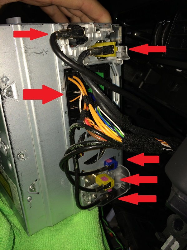
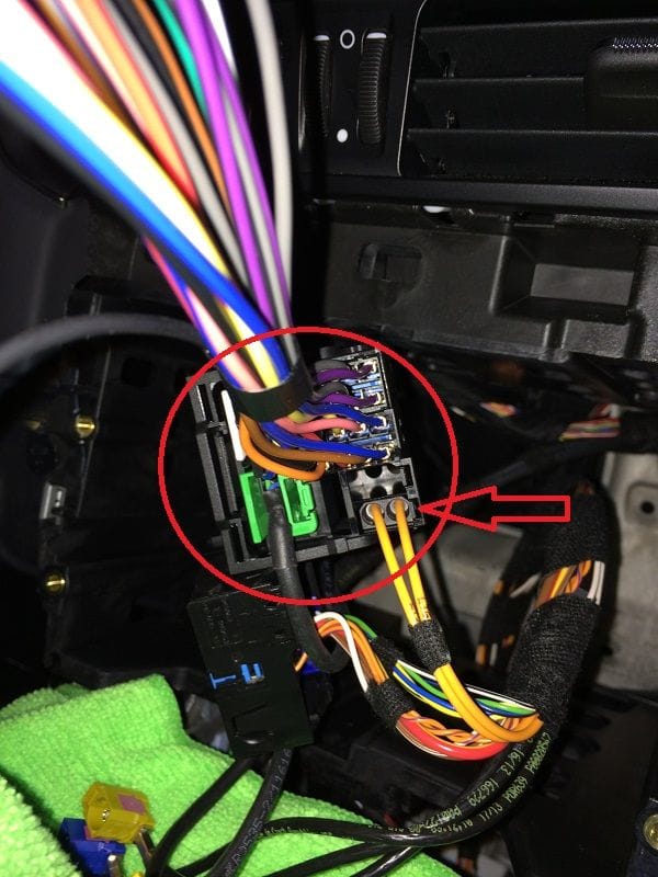
BE PATIENT! Some of the connections on my unit were downright stubborn and I had a tough time with my big fingers releasing the tabs! There are 6 connection points you need to remove, as indicated by red arrows below:
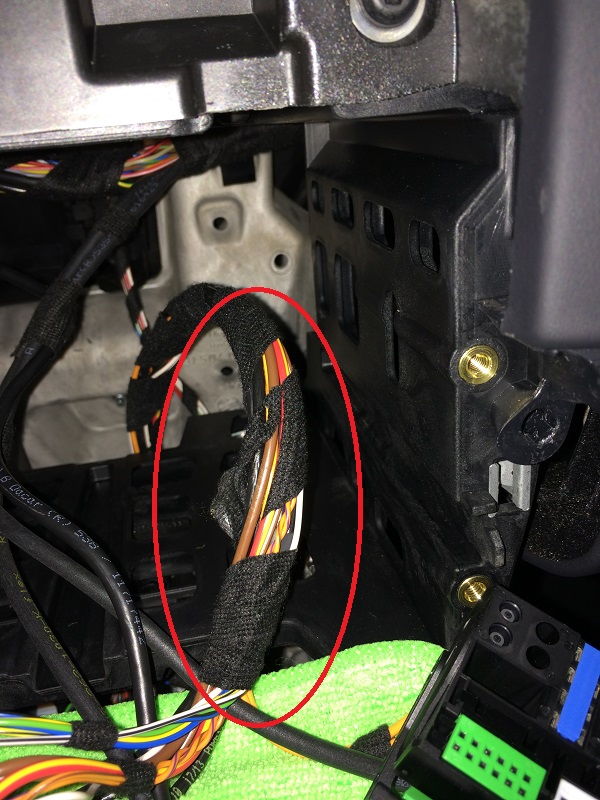
2. Once you have the PCM removed, pull the factory wires as far out of the dash as you can. You may also want to carefully remove the factory tape wrapping the wires into bundles, so that it is easier to work with some of the individual wires. This will be important later when you need to push the wiring back into the dash cavity.
Following steps are included in the NAVTV instructions booklet -- but maybe my version will help a little more where they are vague....
3. Once you have the PCM unit out of the way, look at the factory 40-pin black plug, and locate the ORANGE fiber optic cables (2) and the factory GREEN connector. Pull them out of the factory plug. These 2 connectors must be reconnected into the NAV-TV plug-and-play harness for pass-thru.
4. Plug in the white, 8-pin connector from the Plug-and-Play Harness supplied by NAV-TV to the white 8-pin connector on the CAN Adapter Harness.
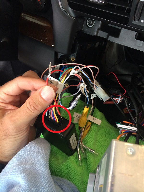
5. Connect the 18-pin black connector from the CAN Adapter Harness to the CAM module (black box).
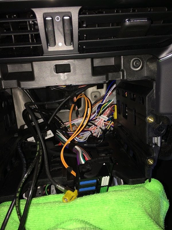
You should now have the factory 40-pin connected to the NAV-TV 40-pin plug-and-play harness, which is in turn connected to the CAN Adapter harness, connected to the CAM module.... You're probably wondering why there are so many "extra" connectors and labeled wires on the CAN Adapter harness - you can ignore them. Other than a couple of wires mentioned later in this DIY, most are just not used in this single-camera installation.
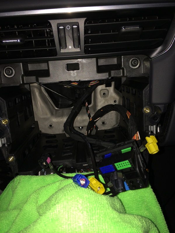
6. Double-check all of your harness and module connections. Push the CAM module back into the dash opening and out of the way. I found a good space behind the drivers-side lower dash area... Don't hide it just yet, but make sure everything is accessible for when you re-install the PCM unit.
Take a break, stretch, and put the dash install aside for a bit.
Run Video/Power Cable: This turned-out to be both the easiest and hardest part of the installation! I began with locating a suitable path through the rear of the car to a point just inside the passenger taillight cavity.
You may find other paths, and maybe your way will be easier, but this was in my opinion the most logical. No reason you couldn't run the cable down the driver's side and I believe it would be exactly the same. I had considered running the cable down the center of the car, but ultimately was trying to avoid pulling-up any carpeting or insulation, or having to remove more interior trim pieces than necessary!
1. Remove the rear passenger taillight (steps not included here -- I'll post separately...).
2. Remove the interior trim piece along the bottom of the rear window. Removing this trim piece is very simple -- just work your fingers behind the trim and tug. I found moving side-to-side and then pulling hard the piece just popped-off. Just take your time, pull more from center, and don't pull entirely from one end, or you may bend or break some of the tabs in other spots.
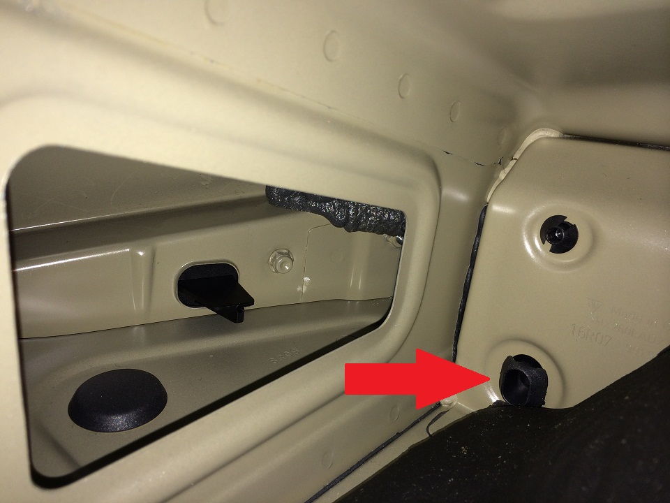
3. Shove your hand deep into the corner behind the side trim panels- if you push the lower trim piece back far enough, you will see two black plugs.
The plug I chose to use was the upper, smaller plug. It was a tiny bit easier to reach, and I felt was in a better spot overall to run the wires thru to the taillight cavity.
4. Push a hole through the hard black plug, giving enough room to get the small 2-pin molex and cabling through. You will need to use something pointy to push through this plug -- it is a hard rubber or plastic. You could also just push the entire plug out, but I wanted to keep some plug "integrity" so I used a pointy-end of a coat-hanger to push through, then wiggled enough to expand the hole. You could also use the Dremel or hand drill to do the same.... in hindsight this may have been easier, but I wasn't sure I could get my big hand and Dremel back there together. The pics make it appear as though the space is cavernous when in fact it is quite tight back there.
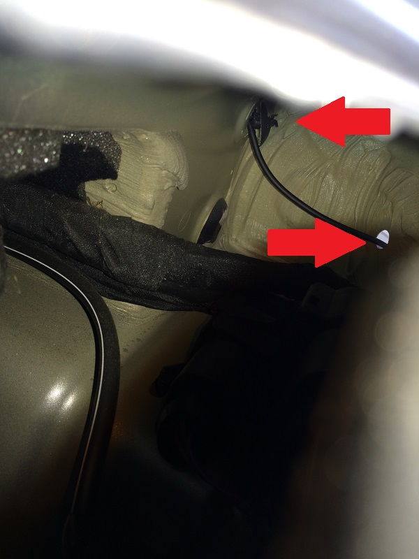
Here's a pic of the coat hanger coming through into the space directly behind the plug.
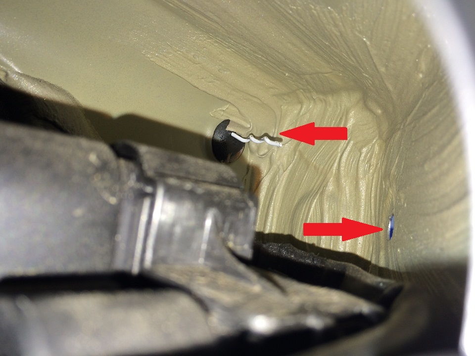
The arrows in the pic indicate the entry point on the left, and the destination hole (conveniently not plugged) on the right. This is the path we'll follow when running the cable.
5. Carefully push the camera-end molex of the video cable through the plug/hole from the interior side. Go outside the car to the taillight cavity. You will have to fish the wire out to the exit hole into the taillight area. Push a bunch of the video cable through the hole, and then use a coat hanger with a "hook" on one end to grab the wire and pull through. Again, be careful not to damage the tiny molex connector on the end of the cable.
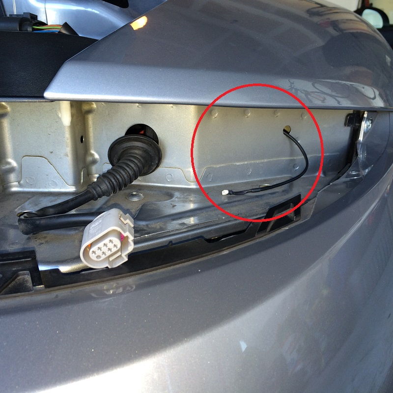
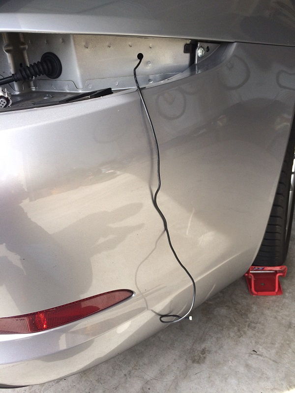
This pic shows the cable running from the plug to the taillight cavity entry point:
6. I pulled just enough of the video cable through into the taillight cavity to be sure there was enough slack to reach the camera connector, and tuck down inside the rear bumper cover.
7. Route the video cable: I started routing the video cable from the rear to the front. The path I chose was behind trim side panels, up and over the passenger door/window, and then down to the dash area. Most of the rubber weatherstripping pushes to one side easily. No PICS of this - sorry.
8. When you reach the front of the passenger door frame, locate a suitable path to get the wire behind the dash. I found trim gaps at the side of the dash where I could easily push the cable behind the dash / carpeting in the passenger foot-well.
9. Run the cable all the way over to the PCM cavity in the dash, and pull out through this opening so that you can work on completing connections for video and power.
NOTE: In the following, I describe how I wired-up the power to the camera.... I did NOT follow the recommendations of NAV-TV. You may want to. They told me (I contacted them directly) to run power to the car battery through a relay. I didn't feel like going to that extent and figured I would try using the supplied power output from the NAV-TV harness. I did discuss my approach with Bob at NAV-TV support, and he told me that while my way would work, eventually the CAM module might "burn-up" and need to be replaced. Probably not warranty either..... I am not too concerned with this, but please consider your own comfort with the risk vs extra effort to wire to another power source.
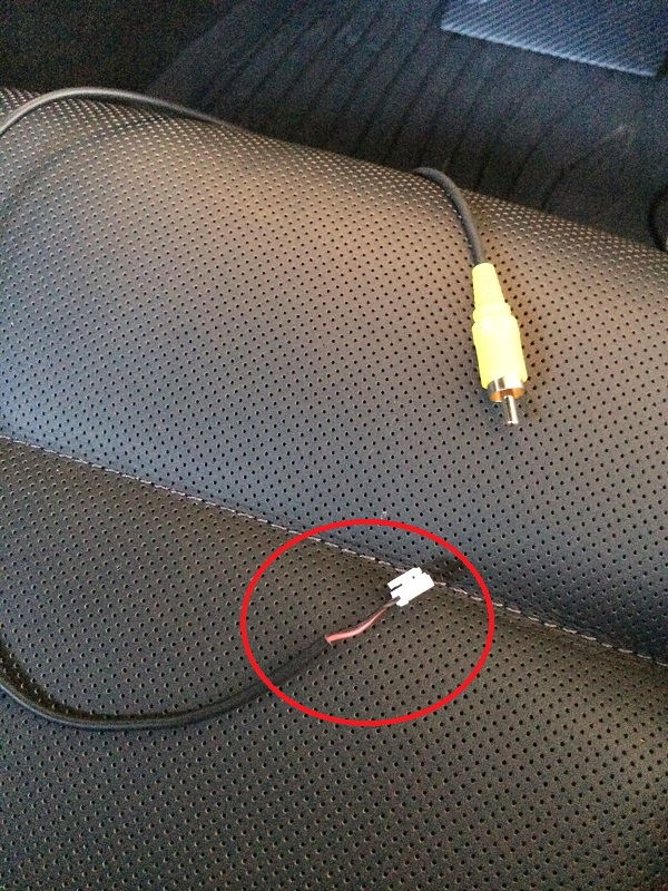
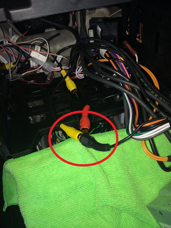
10. Take a hold of the cable you just ran through the to the dash: There are two connectors at the end of the video cable - one being the RCA video that will be connected to the NAV-TV Plug-and-Play harness RCA, and the other being for power....
You will need to snip-off the two-pin white molex connector from the power line so that you can change the connector. The power line includes RED +12V and BLACK ground. With the molex gone, carefully slit the insulating sleeve and pull the red and black wires apart. Trim-off any insulation that is now hanging loose and discard.
11. Connect Video Source: Take the YELLOW RCA male video connector from the camera cabling and plug it into the BLACK RCA female plug coming from the NAV-TV 40-pin plug-and-play connector. Ignore any other RCA connectors. They would be used only if connecting other video sources.
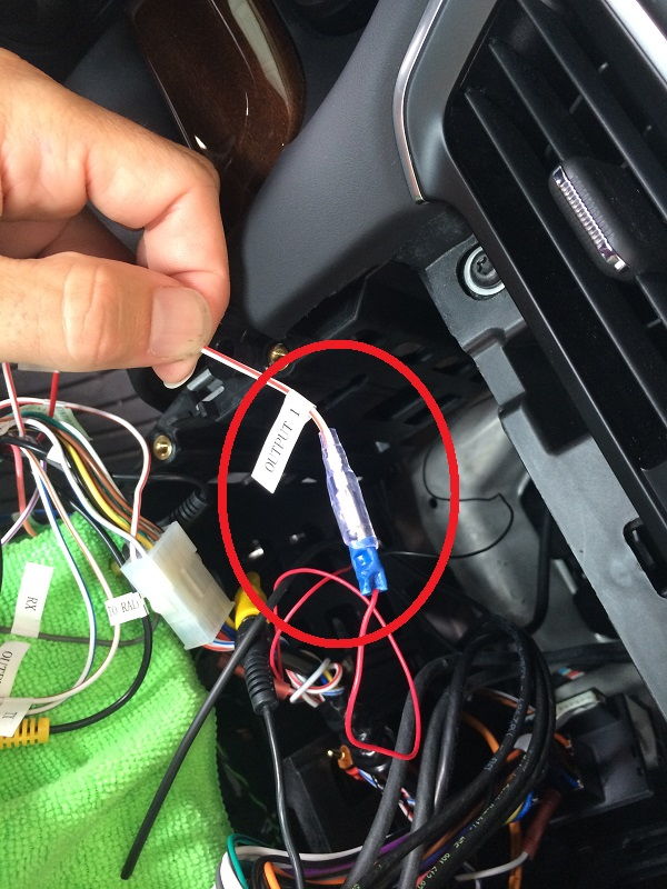
12. Connect Power to the Camera: You will need to make a decision at this point : Either A) connect the power cable to the CAN Adapter harness directly, or connect to another power source, such as the battery or the fuse box. It was recommended by NAV-TV to connect the camera to a separate power source, even directly to the battery through a relay. I was planning on connecting my install to the passenger fuse box with a fuse-tap, but after some discussion on another thread I decided to try connecting the power cable directly to the NAV-TV Adapter harness. There is a power feed there, a white/red wire that is labeled as "OUTPUT 1".
13. Connect RED power wire to NAV-TV OUTPUT 1 labeled connection: To do this, you will need to modify the end of the power cable to the camera. Where you removed the molex, take the RED wire, and install a standard bullet pin connector (of the appropriate size - I think 16 or 18 gauge). I highly recommend you solder the connection between the RED power line and the bullet connector.
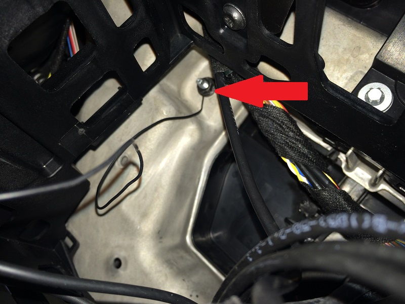
You will then be able to directly connect the camera red wire to the NAV-TV "OUTPUT 1" red/white wire. I then ran the black wire from camera to ground. I found a screw in the firewall area that was in bare metal, so I just loosened and connected my ground there....
Power connection:
Ground connection:
That's it for Part 1. Check out my Part 2 post for the final steps of the project, and some pictures of the installed camera in operation.
This is the 2nd part of the Rear View Camera Install project. If you haven't already, please visit Part 1.
In previous steps, we've removed the PCM, wired-up the NAV-TV adapter and harness, run video/power cable to rear of the car, and connected same to power and ground in the dash.
Let's keep going!
I forgot to mention in the previous step, that after connecting power wire, I wrapped the connection with electrical tape.
I checked all of my connections with a digital multi-meter to make sure I had proper power levels and such. You don't have to, but why wait until you think you are finished to find out something is screwy???
Leave everything at the dash for now. Once you have the rear camera installed you will have to access the CAM module to program the PCM unit, so just leave the wires as-is for now.
Install the Rear Camera:
1. At rear of car, remove license plate.
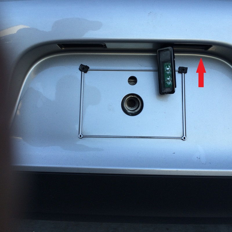
2. Remove one or both license plate LEDs (I only removed the one on the right)
Disconnect the light and place aside. Push the light wire out of the way using your fingers poking up and directly above where you are going to drill the camera mounting hole.
3. Mark the center point between the LEDs. In my crude measurement, I found that the distance between the inner-edge of each light housing to be 4". I marked center with a grease pencil. This is where you will start your hole. Oh, by the way, the CAM 6 comes packaged with a cutting template and weather seal sticker. I didn't use the template for anything more than measurements of the diameter. But you could stick it on and cut-out from there. I didn't.
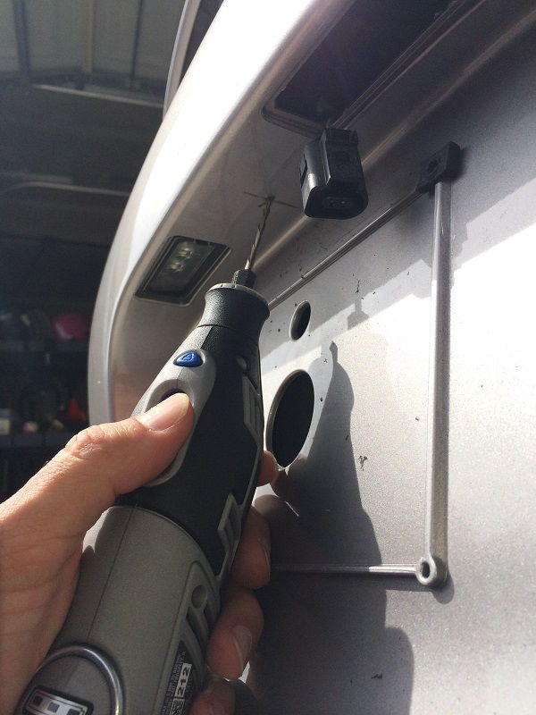
4. Using an appropriate drill bit, make your center point hole. I used a Dremel tool -- be careful to keep the speed appropriate so that you aren't just melting the plastic around the bit. Punch through and remove.
5. I then took a progressive-diameter drill bit, and began widening the hole. I found that the bit was very sharp and using just my hand and gentle pressure I was able to expand the hole to nearly the correct diameter for the camera without using my drill. To get the hole just right (you definitely don't want to go too big!) I then used a couple of Dremel cutting bits appropriate for plastic to quickly get the diameter just slightly smaller than required. I wanted a weather-tight fit! Smooth-out any rough edges around the hole. I also checked up inside the hole for any obstructions just to be sure, then test-fit the camera.
6. Mount camera: First, take the camera and attached cable, and put the weather-seal sticker onto the back of the camera. Just pull-off one side of the paper (I chose the white side!) and stick it on. Of course you need to pull the cable through the hole to get the sticker down on the camera base....
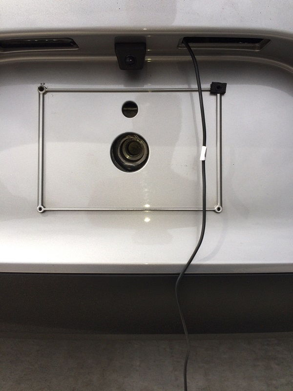
Then pull the cable up and through the new mounting hole, and out from the LED light housing opening.
Make sure to thoroughly clean the mounting surface area. Then pull the weather seal backing off, and push the camera housing into place through the mounting hole. Press firmly. If you got the hole centered right, the camera should look factory...
Take the mounting screw ring, put the camera cable through the center, and push the ring up into the LED light opening. This next part is tricky, but take your time! You have to blindly position the screw-ring into place so that it threads onto the camera mounting threads, and tighten-down. You will only be able to do this with one or two fingers -- but if you remove the left-side LED unit you may be able to use a finger from either hand to position. After a few minutes, I was able to get the threads engaged and tightened it down. The camera housing is now fully-mounted!
7. Pull camera video cable/connector through to taillight area: I used a plastic zip-tie that I modified to use for pulling the cable. Pull the wire out to the taillight cavity. There is a LOT of space in the bumper cover area -- just keep the cable to the "outside" of the air filter housings and away from any of the heat shields further below.
When you have the cable through, you can connect the small molex connectors.
In this picture I've pulled the cable through, and I chose to install cable conduit to protect further from any environmental issues like heat or water. Note I did the same to the cable running out from the car interior...
I also plugged the hole in the taillight cavity to keep the wire from rubbing and possibly cutting through the insulation on the hole opening.
8. Carefully push the video cables down into open space in the bumper cover, and out of the way from the taillight mounting points. Once all is hidden, you can replace the taillight.
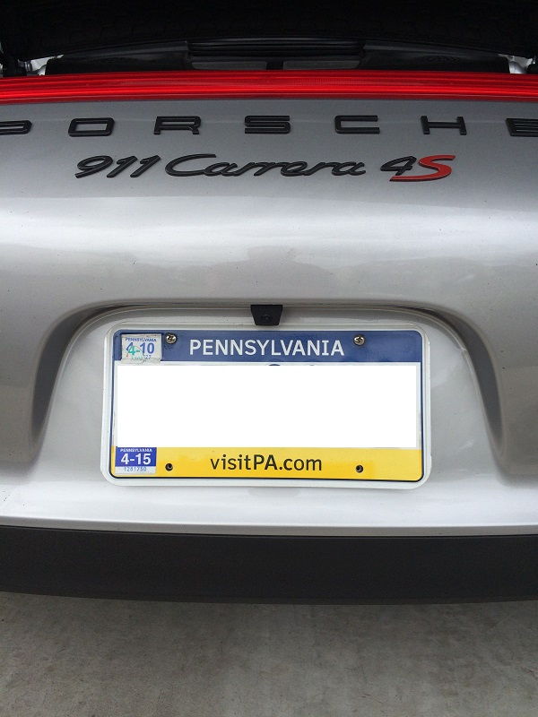
Here is the finished camera install, with my license plate back in place. I thought it came out "factory!"
And here is a pic of a Turbo S with the camera from factory -- looks the same, right????
But wait! We are NOT done just yet! We have to go back to the cabin, connect the PCM unit, program the camera, and TEST!
Program and Test:
1. Back at the dash, grab your PCM unit and connect the NAV-TV Plug-and-Play harness 40-Pin connector into the back of the unit. Then connect each of the remaining factory cables you removed previously. You can check the unit by simply turning it on, making sure that radio, other features still work as expected.
Leave the PCM unit turned "ON" for the next steps...
NOTE: As mentioned at the start of this DIY, some of the steps I follow to program the PCM unit to recognize the camera are specific to the fact that I do NOT have factory Park Assist or Multi-Function Steering wheel. If you have either of those options, you should consult the NAV-TV instruction booklet to complete programming.
Next few steps are specific to my situation and install!
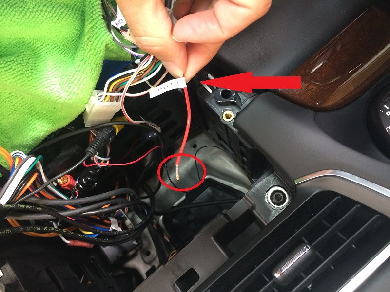
2. Locate a RED wire that has the label "INPUT 1" coming-off the CAN Adapter harness.
Cut-off the female connector that is on the end, and strip the wire as shown in the pic below:
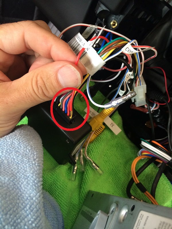
3. Take the black 18-pin connector attached to the CAM module and locate the yellow wire in the lower-right corner (see pic- I am not sure if this is pin 1 or 18 to be honest....)
To set the PCM programming for the camera, you will have to "PULSE" INPUT 1 to 12v within 10 seconds.... To do this, take the stripped-end of the INPUT 1 RED wire and simply push down into the pin connection between the yellow wire and the module (see pic)
There are other ways to do this, such as stripping a portion of the yellow insulation and touching to the bare wire, but I didn't want to do that, so I pushed down into the connection pin.
If you get the PULSE right, you should see your PCM unit reboot. It may take several minutes to come back-up. If it doesn't reboot at all, you didn't get the PULSE right, or something else is wrong. Took me two attempts!
Once the PCM unit reboots, you can check that the programming worked as follows....
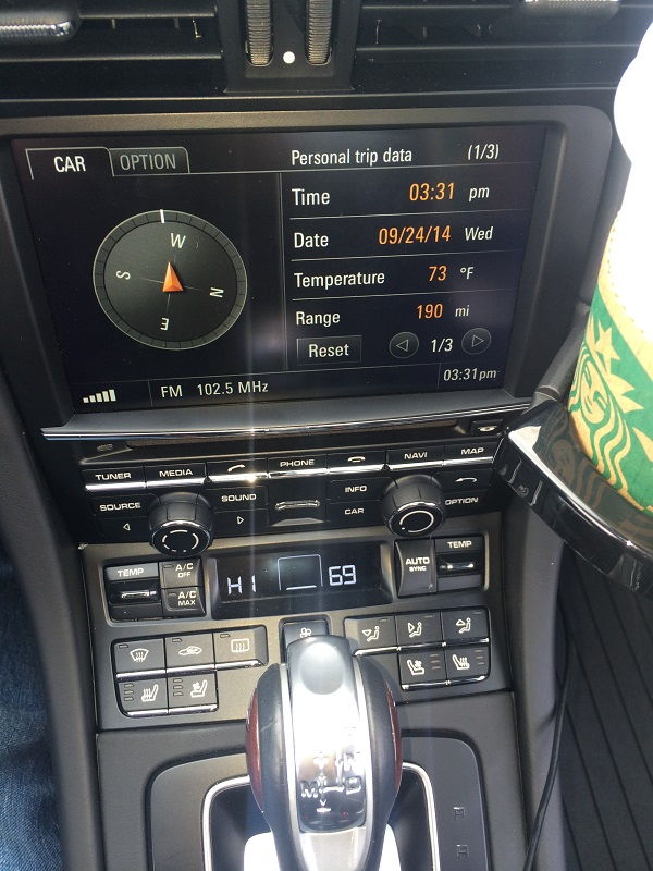
4. Go to the CAR menu screen, and then choose OPTION.
5. On the OPTION screen, you should select SET CAR
6. On the next screen, you should now see a new menu option - SET REAR VIEW CAMERA
Select this option.
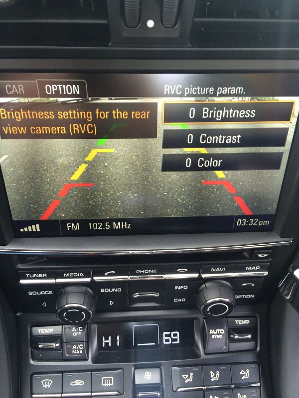
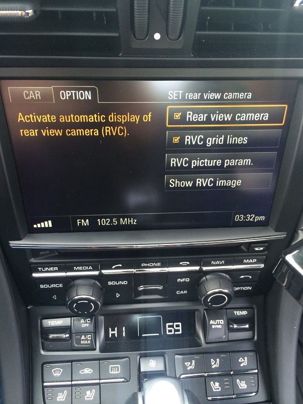
7. You should now see a new menu screen with options for activating the automatic display when selecting reverse gear, camera settings, and even an option to force camera on (more on that one later).
Here is a pic of the RVC picture parameters...
If you see all this, your programming was successful!
So let's button things up and complete the project!
1. Make sure to "cap" the INPUT 1 RED wire you stripped for the programming. I clipped-off the exposed wire, folded the wire back and wrapped with electrical tape. Boom.
2. Carefully push the NAV-TV black box and all wiring as far back into the dash cavity as you can. Try to push the black box down as well, all the way at the rear. I found there is a lot of open space just behind the driver-side dash to store the NAV-TV black box. If you don't get the box and wires far enough back and out of the way, you won't be able to get the PCM head unit back in, and you don't want to push too hard (potentially crimping a wire, or breaking something....). I chose to strap-up as much of the wiring as possible neatly so that there wouldn't be any stray connectors getting in the way of the PCM unit.
3. With all the wiring safely tucked away, carefully fit your PCM unit back into the dash and tighten-down with the 4 screws. Re-install the console trim pieces, and pat yourself on the back for completing your project!!!
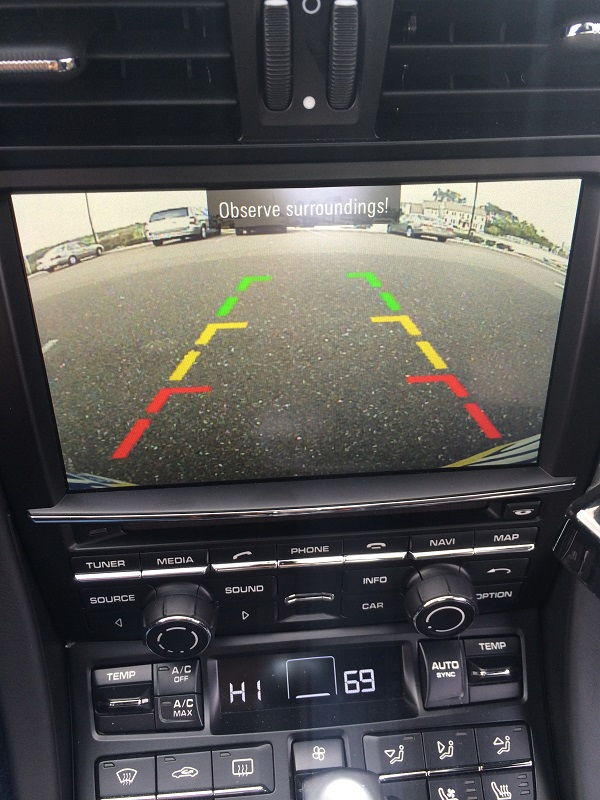
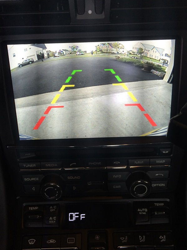
Finally, moment of truth, I started-up the car, moved the PDK to reverse, and within a second the rear picture popped-up on the screen! Looks good IMO, and brightness was perfect. The quality of the image is better than I expected... (my iPhone picture quality isn't all that great tho! )
My license plate was bent a bit, so it is appearing in the lower corners of the image -- I've bent it flat so now I don't see the plate at all. The camera has a good field of view.
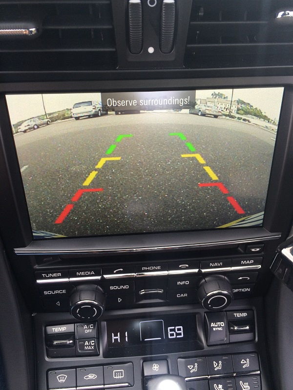
Here is another, while out for a test-run...
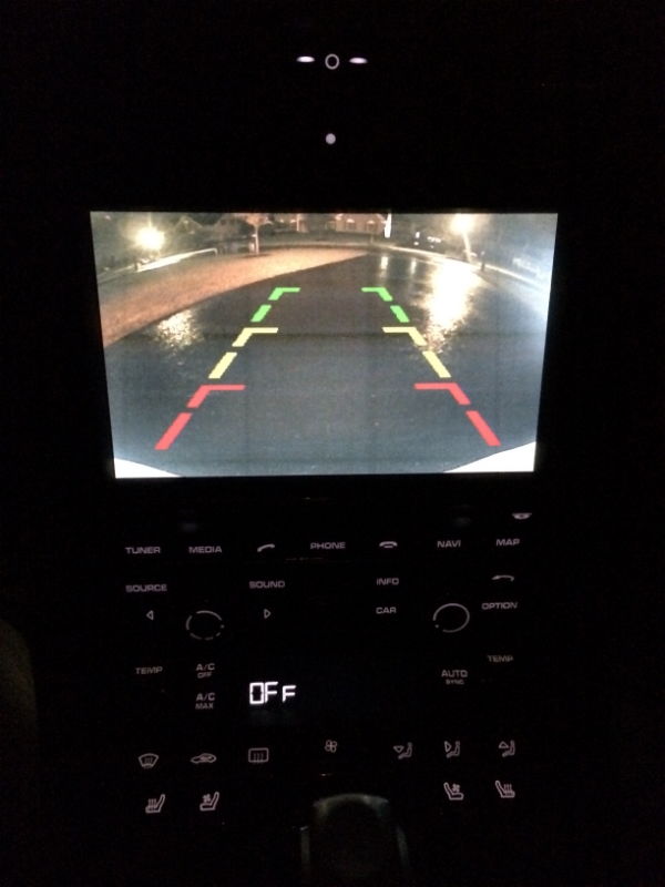
And for reference, for those of you wondering as I was, here is how the image looks at night (dark, rainy night!)...
I found that the image is always coming-up within a second or so when putting car into reverse. What I found tho is that when moving into Drive, the camera will stay "on" longer than I was expecting. I was thinking that maybe something is wrong and the camera was stuck on. But then I noticed as soon as I got to 10-12 MPH the image clicked-off. I actually like this.... As sometimes in maneuvering around the driveway I would like the image to stay-on.
Also, I found that if you are stopped, even if you are not in Reverse, you can force the camera on by going to the Camera Setup menu, and hitting the "Show RVC Image" option.
The image will remain active on the screen until you begin driving, at about 10-12 MPH. Cool!
Well, I hope you found this DIY helpful in your own project. Thanks for reading through!
While it was fun just taking the front bumper cover off my '14 C4S (see DIY - 2014 991 C4S Front Bumper Cover Removal), I actually had another project purpose. I wanted to install custom mesh wire grill screens.
I have the stock or standard non-Sport Design 991 front bumper cover, and the two openings for the radiators are huge! They leave the radiators open to damage from all sorts of debris. Where I live in the NE the roads are awful, and we have a lot of leaves and other stuff on the roads all the time. Yes, it is simple to just stick the nozzle of my shop vac into the opening once in a while -- but that only removes what is loose. I wanted to also protect the radiators from rock damage, and getting insect guts permanently embedded in the radiator fins.
So following are the steps I followed to create my own mesh grills...
Openings in stock bumper cover on my C4S:
I initially intended to follow the lead of fellow members SM_ATL and Jim M. and install some wire mesh from the outside - without removing the front cover. They both have great posts in the DIY section, by the way!
But as I got ready to do the install, I just knew I would not be happy without a very solid, tight, "invisible mount" or factory-look finish. Plus I just love to explore and mess with stuff, so I decided to remove the entire front bumper cover and install my grill mesh from the inside!
I ordered my wire mesh from CustomCarGrills.com. Easy to order, and I received my mesh in a couple of days. For reference, I ordered the Diamond Small Mesh, in a single 12" x 48" sheet. You can order the mesh in Black powder-coating, which adds $10-$15 dollars to the order, but I elected to order Silver. Contact me if you want a link to the product page to order for yourself.
My order arrived in a single flat box... it was well packed and protected from bending or other damage really well. Here are some pics of the package I received.
Once I had the mesh out, I measured to center, marked, and cut in half.
With the bumper cover removed, I began shaping a template to cut the mesh. I started by using some heavy gauge wire and shaped it around the opening from inside the bumper. This was a great tip from SM_ATL's DIY!
I then transfered that to cardboard
After cutting the cardboard (yes, it is a rough!!) I trimmed and test-fit to the radiator opening from inside bumper cover.
Once I was happy with the cardboard version, I transferred to the wire mesh and cut. Sorry, didn't catch a pic of this step! The initial cut was purposely larger than I needed, and then I cut to "fit" in the opening. I also wanted to make sure I had sufficient coverage for mounting points, but also not have material causing alignment issues or interference with ducting when I re-installed the front bumper cover.
Test fitting the cut mesh from inside bumper cover:
As I looked at the mesh in place, I decided to paint the mesh flat black. I had a few cans of Plastidip in the garage, and coated each mesh piece with 8 coats. I have a feeling that the paint may not hold up over time, but honestly I don't mind repainting or replacing in the future anyways...
Once the paint was cured, I then used zip-ties to loosely fix the mesh in place, then turned the cover over and took a look to make sure i didn't have any gaps visible around the edges, etc.
Once I was happy with the fit, I removed the zip ties and used heavy-gauge (like 18) coated wire to securely mount each grill. I first used industrial contact tape to hold the mesh in place, putting tape around the entire opening. This enabled me to fix the mesh in position while I mounted more securely. I then found 5-6 mounting points for each grill and tightly twist-wrapped the wire to hold the mesh in place. The mesh will NOT move, shift, and can probably even be hit really hard by a rock without doing more than bending...
Before I replaced the bumper cover, I cleaned-out the Radiator openings - my 6 month old car with 3k miles didn't have too much junk in there, but we are just entering bug season, and in the fall it gets a LOT worse when the trees begin shedding! And more importantly, you can see the radiator is getting bent quite a bit by the little debris that hits it -- including little bugs.
Right radiator:
Left radiator:
Here's a shot after i mounted:
Remounted the bumper and all other parts I had removed earlier, and took it for a test-drive (started raining at that point, so got a good water test as well!):
Next morning I tried to get a good picture, but iPhone just couldn't handle the morning sun....! But I have to say, I am very pleased with the results of this little project!